Milling PCBs

TL;dr: lots of love and thanks to Poul-Henning Kamp, mattvenn and Nick of CNC-club.ru!
For a long, long time I wanted to replace the tedious chemical process for making prototype PCBs in my lab with something faster.
I tried the direct-toner method: basically you print the layout in 1:1 size on a laser printer, put the paper face-down on the copper of the PCB and heat the whole thing.
The toner will melt again (melting is how the laser printer fixes the toner to the paper in the first place) and the toner traces will form a resist against the acid used in etching.
Sounds simple, but it never worked for me: the toner transfer was never really good, I tried special paper (advertised as usable for laser-printing decals), tried using a laminator instead of the clothes iron etc. No success.
When etching with the usual process
-
-printing a photo-mask (laser or inkjet; I have better results with inkjet)
-
-exposing the photo-resist on the PCB with UV light
-
-developing the photoresist in caustic soda (NaOH)
-
-etching with FeIIICl, HCl+H2O2 or CuCL acid
-
-cleaning off the photoresist with acetone
I see basically 2 drawbacks.
It takes quite some time and during this time you can not really do anything else: each step of the process is fairly short so you can not use that time otherwise.
The second problem is drilling the holes for through-hole components: the drilling position never truly matches the intended position of the hole.
Milling the PCB does not produce a result much faster, especially for more complex and larger boards with many traces.
But while the mill is busy converting copper and FR4 into nasty small chips, you can do something else, work on the next project or maybe even find an error in the layout the mill is currently working on...
Murphy is always watching).
And the drilled holes are in exactly the right place - because they are drilled by the same machine. That is good.
There is only one small problem: the PCB surface is not exactly level.
My first attempt to tackle this problem was to make the machine bed as level as possible.
The idea is simple: place a sacrificial piece of material on the actual machine bed and use the mill to level this part.
The result is a surface that must be perfectly parallel to the XY-plane of the machine by definition: that is the plane in which the end mill moved when making the surface.
This works quite well and is of no help whatsoever regarding the problem of the PCB surface being no level: The PCBs bend when clamped to the machine and are not really of uniform thickness to begin with.
Of course not: precision costs money and for the optical-chemical process they do not need to be level.
Next attempt: a floating Z-Axis like this one.
Does not work, either: Murphy pushes some dust particle, some copper chip in the way and the piece comes out ruined.
No, the real solution is to use the Z-Axis of the machine.
This idea has been discussed in many places, and those solutions are the ones I learned from.
I am using LinuxCNC, so I am not very interested in methods that only work for other CNC controllers.
My method that I will preset a little further down works with LinuxCNC but can easily be modified for other controllers such as Mach3.
I also wanted a solution that works with different layout programs and layout->GCode converters. My conversion filter is currently tailored to processing the output of Eagles G-Code generator; I have done limited testing with pcb2gcode, which takes Gerber files as its input, but again: it should be easily adaptable.
Starting from the LinuxCNC point of view, I found a neat method.
The idea here is to create a HAL component that adds a compensation value to the Z coordinates in the G-Code input on the fly.
It requires some rewiring of the HAL for your machine, to load the compensation component and the toggles to enable/disable the compensation when necessary.
I liked the method, because I immediately thought that it can no possibly work: using a non-realtime HAL component at runtime seemed like a Bad Idea.
Well: it works!
Some details of this solution are also good ideas and I will use them in other applications: using HALs digital IO function (M-Codes 62..65) is cool: who said that M62..M65 could only output to the physical world? They can be used to control HAL (software) components as well.
But I found the method error prone.
When using the HAL-based approach, you must follow a procedure:
-
-turn off Z-compensation
-
-delete the file with the measured height profile
-
-load a G-Code program to measure the height profile of your workpiece
-
-turn on Z-compensation,; this reads in the height profile from the file
-
-load the G-code program for the workpiece
-
-mill the workpiece.
The „delete file“ step must not be missed: the probing code will always append to the file - not what you want at all. Learning this cost me about 3 Dollars worth in broken carbide mills...
After some experimentation, I removed the HAL-based solution from my config again and started using another solution.
Poul-Henning Kamp published an idea and implementation, that he is using with a small mill.
This was discussed in a forum (no link here - intentionally: I consider Web forums a form of torture) and one kind soul (going by the handle mattvenn on Github) re-implemented the idea in Python.
And mattvenn also improved on the usability a lot: a little GUI, some description of the algorithm, selectable machine units (it seems there is still people using machines and thinking in inches, feet, gallons, quarts, pounds and whatnot. Scary!) and a hook to run a path optimizer before adding the Z-probing G-Code.
I liked it - but had to change it.
The „interactive GUI program“ approach is all nice and fine, but it is so non-Unix :-)
I took the code from mattvenn and
-
-stripped the GUI
-
-dropped support for imperial units
-
-dropped the hook for running a path optimizer
-
-replaced the code parsing the numbers in the input file
-
-added some filtering/mangling of the input
and thus effectively made the program into an import filter.
I will probably add the optimizer hook again at some point. But for the moment I do not have access to a program of that kind, so I am not using it.
For now, my script can be found at https://github.com/hase-berlin/pcbGcodeZprobing.
I will continue working at it and have not started versioning.
If you want to comment, improve, share your experience: do so. I am reachable as hase@hase.net.
The script is simple to use.
It takes one parameter: a file name of an input file.
It will then print the modified version on standard output. If you want to save that to a file, simply redirect output like eagle2linuxcnc huhu.ncd >huhu_zcorrected.ngc.
Or modify your LinuxCNC config like so:
in the .ini file for your machine, find the section [FILTER]. By default it looks like
[FILTER]
PROGRAM_EXTENSION = .png,.gif,.jpg Greyscale Depth Image
PROGRAM_EXTENSION = .py Python Script
png = image-to-gcode
gif = image-to-gcode
jpg = image-to-gcode
py = python
Add two lines to make it look like
[FILTER]
PROGRAM_EXTENSION = .ncd Eagle-G-Code
PROGRAM_EXTENSION = .png,.gif,.jpg Greyscale Depth Image
PROGRAM_EXTENSION = .py Python Script
png = image-to-gcode
gif = image-to-gcode
jpg = image-to-gcode
py = python
ncd = /usr/local/bin/eagle2linuxcnc.py
The PROGRAM_EXTENSION line tells axis (I do not know about gmoccapy for now) to include the *.ncd file extension in the filter for the open dialog: with ctrl-O you can directly open the files.
The ncd = ... line tells axis which program to invoke when processing a file of the type, here my little filter.
The script contains some documentation in the source.
I make some use of regular expressions for the filtering (dropping/replacing lines from the input) and for finding the coordinate values in the line currently processed.
Please note:
The script is not heavily tested and I only used it to process G-Code files created by the mill outlines/Fräskonturen ULP in Eagle.
Your mileage may vary.
On the hardware side, I use the most simple probe possible: the PCB is electrically connected to an input pin of my PC parallel port, the mill bit in the spindle is connected to ground.
in the .hal file for the machine, the pin is wired as
net contactprobe => motion.probe-input
net contactprobe <= parport.0.pin-13-in-not
This way, when the mill bit makes contact with the copper of the board, the input trips.
If you have problems, try adding a 10k or 4k7 pull-up resistor between the input-pin and +5V: the parallel port has internal pullup resistors, but they sometimes have quite large values and when running a cable all the way through a noisy environment (like a machine with steppers or servos :-), the internal pullup may be too weak.
So much for now. Questions? Ask!
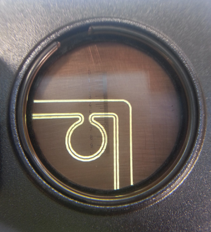
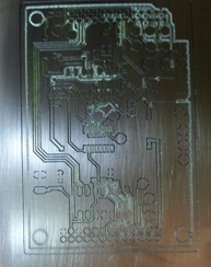
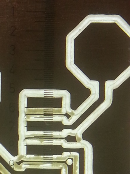
At least, I can now „quickly“ make a PCB in the lab again.
And the traces are consistent, no matter how bent the PCB is.