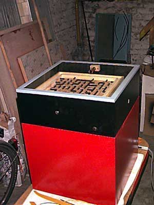
Box two
In 2007 a friend and colleague of mine got married.
I thougt this would be a great time to recreate a wedding gif-wrapping that Matthias and me (well, mostly Matthias, I admit) had built in 1997 - for another wedding.
And maybe this time aroud we could avoid some of the problems the first version of the box had.
The original box (from 1997. Photographed with 1997 digital camera technology, aka Apple QuickTake) had a nice concept but some small design flaws features.
But the general concept of using a Brio Labyrinth as the lock was pretty good:
- the nature of the lock is easy to guess/comprehend
- the unlocking provides entertainment for the audience
- the base rule is automatically enforced
The base rule being - what else - the receiver of the gift must not behold the gift before at least 30 minutes of fiddling with the packaging.
As mentioned before, the old model hat some rather annoying features.
But this time around, the box would be perfect.
Of course.
What else could it be when hase and Matthias team up and decades of engineering experience is thus brought into the project?
Exactly!
I have to comment on the picture quality again.
The Apple QuickTake 100 used to photograph the older - red and black - box was not really state-of-the-art in 1994 when Matthias bought it for the equivalent of one month pay. But it was really easy to use (albeit needing very propriaetary software). And it was wat he had at the time.
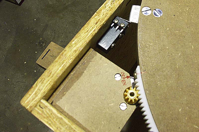
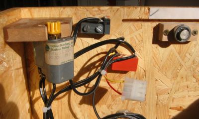
The drive mechanics used in Brio1 proved to be kinda tricky.
The concept is this:
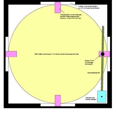
- the motor (to the right) drives a threaded rod (the silver rod parallel to the lower edge of the box).
- The round MDF plate has the same type thread on its circumference.
- Together the threaded rod and MDF plate form a worm gear.
This should work in theory and provide quite some torque, as the reduction of this worm gear stage is huge.
On the other hand, it also proved to provide quite some friction, even with the thread in the MDF effectively turned into plastic (by generous application of superglue to the surface before cutting the thread).
Also the metric thread (designed for screws, bots and nuts, not for worm gears) did not tolerate much play between the rod and MFD plate before skipping.
Little play => high friction.
So this time around, we re-designed the drive mechanism before starting to build (planning beforre building? What a concept!).
The general idea would be the same: a motor driving a threaded rod.
The rod would drive a nut attached to the rotor - again an MDF plate - which would provide low enough friction and really good grip.
The challenges would be the angle of attack between the nut and the rod: with the rotor turning, this angle would change. So the nut could not be firmly attached to the rotor but would have to pivot somewhat.
Also the drive would have to turn all the way until the rod is free of the nut, as the rotor is part of the "lid" of the box and the motor is attached to the bottom part.
Because of these challanges in (his own) design, Matthias decided against this variant and we went for something else completely.
We went for a toothed rack drive, like a cograil.
Unlike the worm drive, this is not self-locking. And I like self-locking gears for wedding present boxes.
But the effect is good enough: the large reduction ratio of the gear makes it practically impossible to drive the motor from the outside - it is effectively self-locking.
The drive does not attach the lid to the bottom: when the rotor is in the "open" position, the lid can be taken off without any hassle. This is really cool.
The toothed rack is store-bought and after milling off some superflous material in its spine and applying some heat, it became bendable enough to be screwed to the side of the rotor.
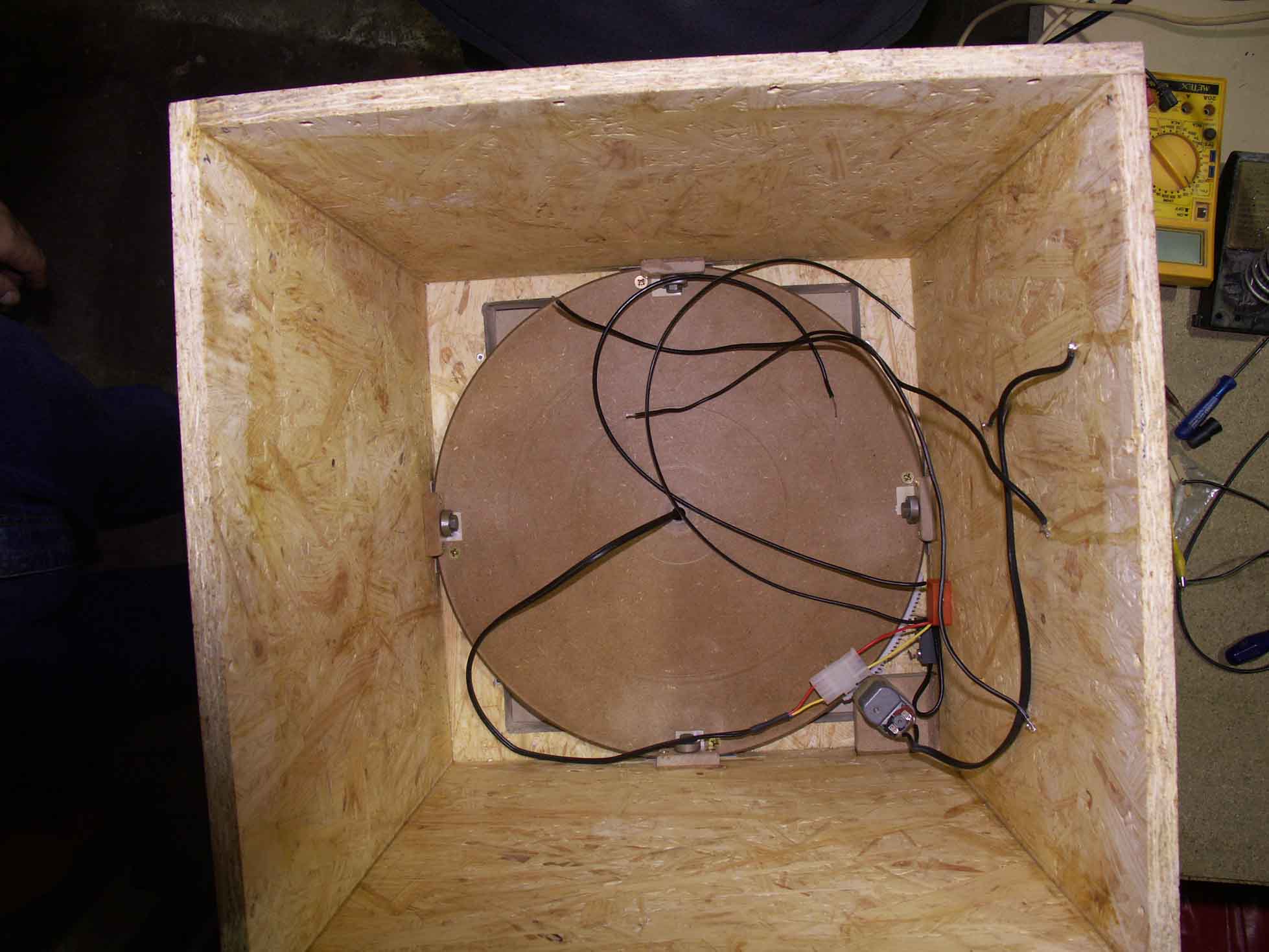
The rotor itself was milled on Matthias Proxxon mill: a square piece of MDF gets a hole in the middle, a bolt is screwed to the base of the mill and the MDF-square is mounted on that bolt. Then it is simply manually pushed against the mill bit rotating in the spindle and thus cut into a perfect circle.
Screwed to the bottom of the rotor are 4 pieces of sheet metal, aliminium in out case (selection process as usual: whatever is in stock and fits the bill).
These aluminium blades grab into slits in the outer wall of the boxes bottom part.
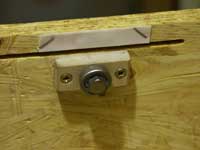
Below the locking slits, a ball bearing is mounted to the wall of the box. They serve as a rollers to support the rotor.
Above the slit a piece of PTFE sheet is nailed to the wall. This serves as a gliding bearing to hold the rotor in place between the box walls.
PTFE can not be glued, so it is nailed in place - problem solved.
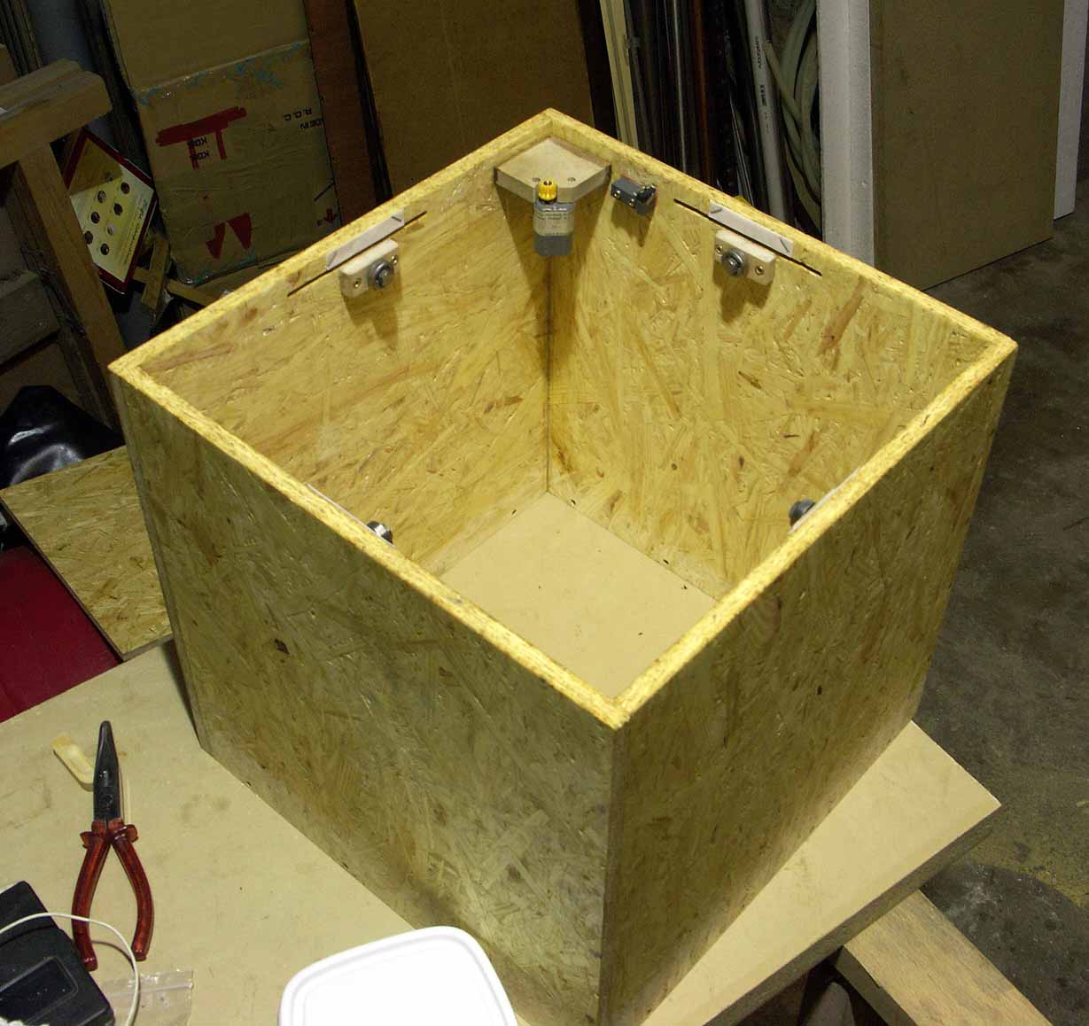
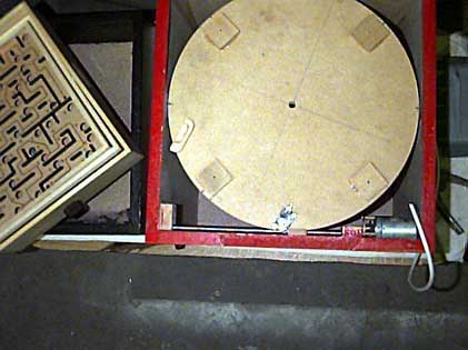
The motor is simply located in a corner of the box, the pinion grabs into the toothed rack and this way we can turn the lokcking rotor back and forth.
At a rather majestetic speed due to the high reduction of the effective gear ratio.
The four ball bearings support the rotor and allow it to turn freely.
Murphy at work
Or rather: poor planning.
When discussing the project with Matthias - my usual partner-in-crime for something like this - I asked him what to shop for.
A motor?
"Nooo" he said, "I have plenty of old DC motors lying around".
Indeed, he had a motor with a pinion attached to it and the fitting toothed rack as well.
Only: the motors rated voltage is 30V (where the heck does he get this stuff from? Pollin?).
So instead of the original plan - run the box on a 6V battery - I had to use 4 batteries to provide 24V for the motor (and 6V for the relais).
Great.
In the picture showing the pinion grabbing the rack you can also see the black microswitch used as the end-switch for the rotation. This simply cuts power to the motor when the rotor has reached the "open" position with the aluminium blades free from the locking slits in the box wall.
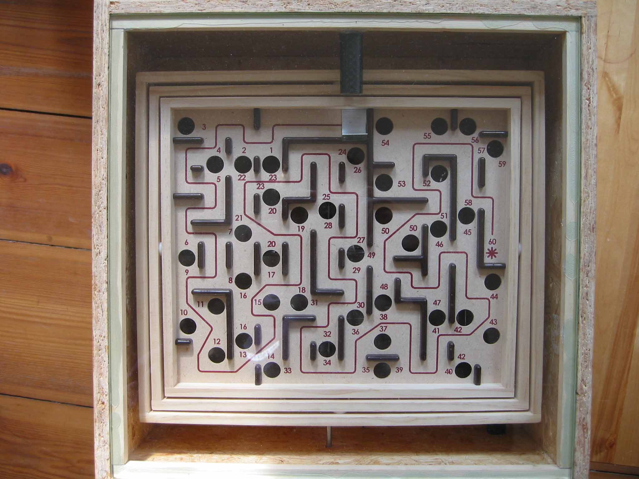
The opening motion is triggered by a contact below one of the holes in the Labyriths cardanically mounted plate.
So the ball must be wiggled all the way to the appropriate hole, sunk there and the box opens.
In Brio1 the contact was two copper rods.
The concept was for the steel ball to close the contact between the rods, close the circuit and conduct power to the motor.
This did not work well:
- copper is a shitty concact material (and is never used for that purpose for exactly that reason). Within a day or so it is oxidized enough to provide basically no contact.
- while the rotor - which contains the Labyrinth - is turning, the whole thing rattles and vibrates. So the steel ball will rattle on the contact, even if the contact is made (e.g. with silver contacts). This results in jerky-jittery motion and a totally underengineered (someting seems wrong here) sound.
Having learned that lesson, I insisted to use a good contact.
A microswitch provides a good contact: the innards use something appropriate as contact surfaces (not copper, Matthias!) and the spring mechanism makes solid, non-jittery contact once it is sprung.
Well, if it is sprung: the weight of a 14mm ball of steel is not enough to spring the microswitch.
Dreck.
But it is still Saturday, the shops still open and I could shop materials for a Plan B or C.
Plan C would be a photoelectric barrier. These work fine and reliable.
But they also draw current all the time.
Lets first try something else.
A variant of the old copper rods - just not with copper.
Brass was available in the workshop, lets make a contact from that and try it out.
The results were encouraging: this was good enough to provide some current and stainless stell worked even better.
Still the problem with the jerky motor motion caused by the ball rattling on ton of the contact rods was very much present.
A relais with 2 contacts solves this problem.
One contact provides power to the motor, the other one provides power to the relais coil. So once the relai is activated, it keeps itself active.
The end switch simply cuts the power to the relai coil, so it deactivates again when the box is open.
So that seems to work well after increasing the bore on all holes.
Wait - why increase the bore on the holes?
Because Mathias somehow managed to loose the steel ball that came with the Labyrinth.
And modulor does not have 14mm steel balls.
15mm was the closes match, so all holes needed to be enlarged a little.
Btw. I kinda love-hate modulor.
I seem to be unable to go to this shop and spend less than 100€.
There is kust tooo much materials around providing tooo much inspiration...
Back to the project at hand.
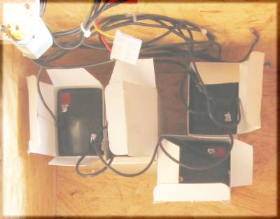
Everything wired up correctly?
Yes, looks good: chaotic, confusing, botched - perfect!
And with the lab power supply everything works fine, lets check with the batteries.
One more lesson learned from Brio1 (the old model, remember?) was this: Battery holders fail.
Somehow they work just fine in all the devices I buy, but when I used them in a time-critical project like this, the plastic breaks or the contact is iffy or whatnot. Fails.
Soldering wires to batteries - in general - does not work.
To make a good solder joint, the material to be soldered must be hot enough, roughtly the melting point of the solder.
If you heat the round knob on a AA or C or D-Cell to the melting point of tin, you will have heated the innards of the battry to a point where it gets damaged.
So you may just end up with a good joint to a bad battery - which is not very helpful.
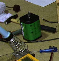
Lantern batteries on the other hand have these spring contacts that are thermally far enough from the battery chemistry. And they are made from a wire that can be soldered on.
That made them my choice for the project.
I had planned to use one of these, but now we need 24V for the "no need to buy one, plenty lying around"-type motor.
Well, 4 it is then.
Lantern batteries are reliable.
A large capacity provides for a long runtime and plenty of discharge current capacity, which usually scales with cell size: the bigger the cell, the more current it can support (when comparing identical chemistries).
So they should be an excellent choice for a project like this one: plentiful and reliable.
Unless you buy them from Conrad in Berlin.
Conrad seems to imagine these batteries to be like good wine: getting better with age.
But battery chemistry is not based on wine, it seems.
They are not getting better with age, it seems.
The label reads "6V".
The multimeter reads "6V" when measuring the battery.
Without any load current.
With the motor running at full power (a whooping 200mA current!), the batteries drop to about 4V each - and 16V is just not enough to get this little motor excited enough to turn.
Dreck.
Luckily it is still 2 full days to the wedding - plenty of time to fix this problem.
And plenty of time to contemplate the lesson: lantern batteries are pfui.
Never again!
Lead accumulators cost about 8€ for the cheapest type readily available 6V-type at a store (Conrad again, when will I learn? :-).
Using 12V or 24V accumulators was out of the question: the relais was already glued into the box and wired up and has a 6V coil.
So quickly buy 4 rechargebles, charge them over night, glue the cardboard boxes they came in to the floor of the box (hotmelt glue for the win!) and solder some wires to the contacts.
This is - in theory - as tricky as soldering to batteries, but still works if you make quick work of it and cool down the joint immediately after it has been made.
Yes, the wires are soldered on: never trust a plugged contact.
Especially when there is no 6.3mm pluigs to be found anywhere ("I am sure I had some left, probably in that bisquit-box over there? No? Too bad.").
Effectively the rechargebles became my wedding present for Toby: I knew he needed some new ones for som solar-powered off-grind thingy.
And while we are at fixing things: the microswitch used for the end-switch lost his actuation lever somewhere in transporting the box from Matthias workshpop to my flat.
Luckily its a standard type and a spare was available.
Time for some final testing.
And for findin out that the holes now all fit a 15mm ball, but around hole 6 there is abarrier close to the wall.
Too close for a 15mm ball - oh no!
So sometimes you just have to get lucky.
The company that me an Toby worked for in '07 employed a cook.
An she diod not only cook really good food for us every day, she also is a part-time jeweler and has steel balls of different diameters at her workshop.
Including one of 13.9 mm she could contribute to this wedding gift.
Phew.
And many thanks again, Bea!
boys and toys
Of course, when you bring something like this to the office - for handoff to the colleague who was volunterred to be the courier to the actual wedding - it will attract some attention.
And will attract boys engineers
and software developers
to fiddle with it.
It's quite tricky to actually solve the lock - 41 holes in between the start and the glory.
That is why I added one feature to this version of the box.
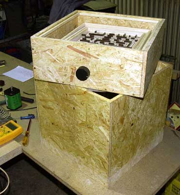
The box is made from oriented strand board (OSB) for stability and good looks.
And it is not painted - quite on purpose.
The chaotic look of an OSB surface makes it easy to hide small details like four brass nails.
They are hard to spot, even when you know where to look.
These nails are part of the wiring inside the box. You can see them in the wiring picture above: they go through the right wall of the box.
Two of them can be used to provide power to the motor from the outside.
This allows for immediate opening
and closing
as demonstrated by me to bewildered colleagues.
The other two are in parallel to the internal accumulators: this way the whole device can be powered from the outside for testing without draining batteries.
It worked
And it was fun to make.
And I think, Toby and his wife liked it.
At least, he said so: "hases box may have been the greatest wedding gift we received. We tried for about 15 minutes and both could not open it. So naturally all the kids present at the wedding wanted to crack the puzzle.
The tried and tried and succeded eventually."
So it turned out, my gift was'nt 4 rechargeble batteries, 2 bottles of wine and a Brio Labyrinth after all.
It was about 3 hours of piece and quiet for all the parents at the wedding and the same time of fun and games for the younglings.
Remember that when next time you are thinking about the perfect wedding gift :-)