Mechanics
Mechanics
Now for the real fun part of the whole thing. We will have something moving on command. Hopefully.
Of course all these contraptions work just fine (
From original Idea...
As described above, the original idea was to open and close a drawer using a motor. But there is always the problem with tolerances. Basically: I could not figure out a way to reliably create the opening and closing motion.
And sometime later I thought that a lifting/lowering motion may be even more spectacular.
... to implemented concept
That is when in my head the Mackis box turned to stand on the fronts oft the drawers. Such, the drawer-opening motion would become a lifting motion for the entire box, the closing would become the lowering motion.
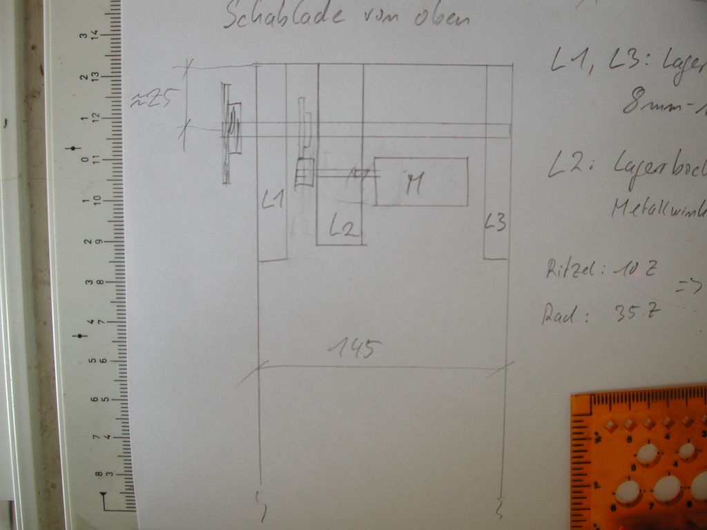
A quick sketch of the drive with some of the measurements. A freehand-sketch like this is always helpful.
It is not really a technical drawing. Much of the necessary information for contructing the drive mechanics is not in here and nothing is really to scale. And the gears in the sketch are made from glass, not steel :-)
Still, this overview was helpful for the design and also for communicating with my partner-in-construction, Matthias.
The orange thingy you see on the bottom left is my beloved Rolimin, a roller-ruler that I used to use on a daily basis about a decade ago. I use it less these days but for the quick-and-dirty sketches it is still very helpful – and the system pencil+Rolimin+paper is still faster than Windows+Illustrator+Deskjet.
My plan was to construct the bearing blocks L1 and L3 from wood with 22mm bores. In the bores I would place ball-bearings for the 8mm shaft driving the sprocket that is seen to the left of the drawer.
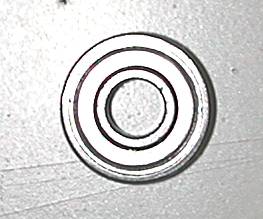
The 8mm/22mm ball bearings (type 608ZZ) are dirt-cheap and very solid, actually. They are bearings used in rollers for in-line skates or similar devices. For a while, the cheapest way to get 608ZZ bearings was to buy inline-skate replacement roller from Pollin and pluck the bearings from those. Nowadays I simply buy them off an online marke in quantities of 50 or so - which lasts for one or two projects. And the bearings are even fully sealed types, pretty much dustproof.
They are designed to carry loads like a 100kg person on 4 bearings (scooters with 2 rollers). Sufficient for our purpose here, I guess.
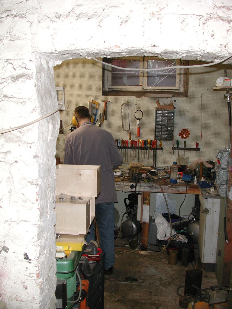
But my workshop is not equipped for machining large objects like these, so I had to turn to Matthias.
I am always all-green with jealousy when I see his workshop in the basement of his house.
This has changed.
When Matthias had to move (he moved out of the house), we teamed up, rented a small workshop together and now I have access to all his gear :-)
And he got access to all my electronics lab equipment out of the deal.
Matthias has a Proxxon lathe (to the left behind the wall) and a Proxxon milling machine (behind Matthias) in there, both of which we used for some of the work described below.
The plasma torch and WIG welding equipment we did not use on this project. Hmm. We'll use it on the next one, I guess :-)
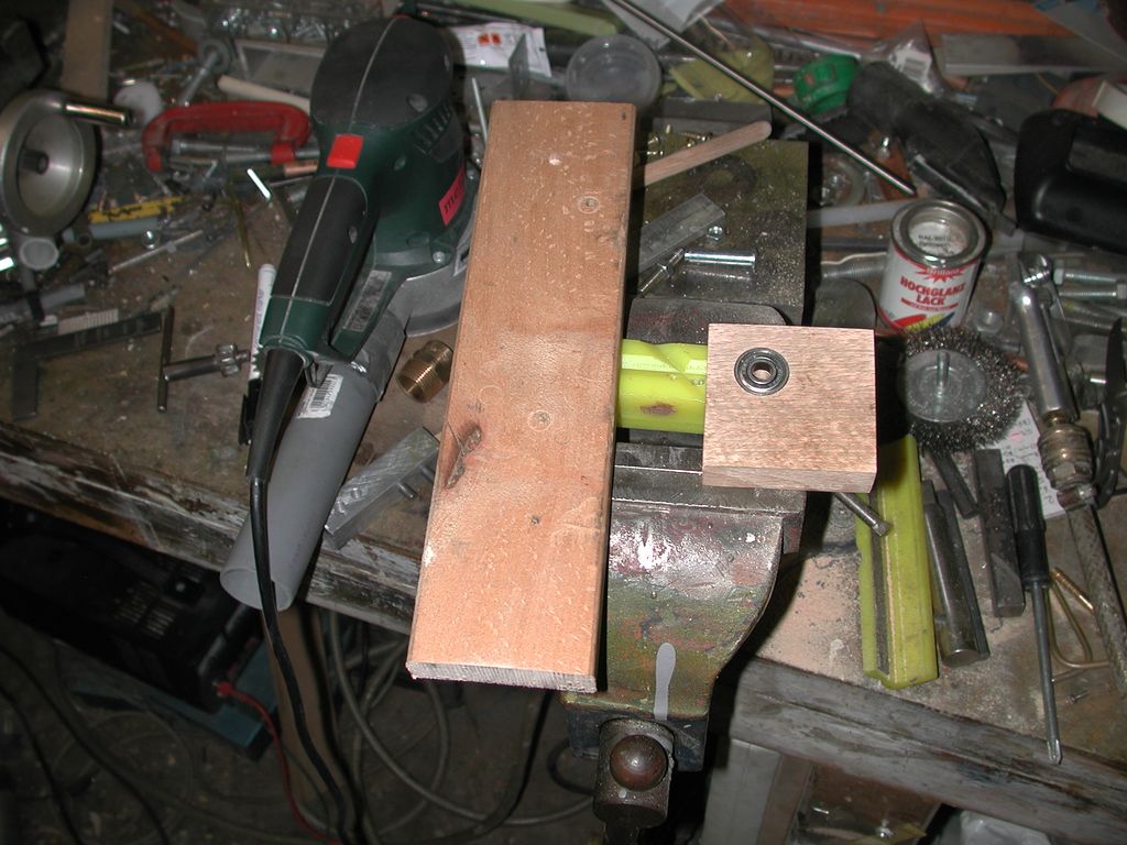
A bearing block (with the ball bearing already pressed in) and the raw material it was made from. The scrap piece of beach wood was lying around, waiting for an opportunity like this one.
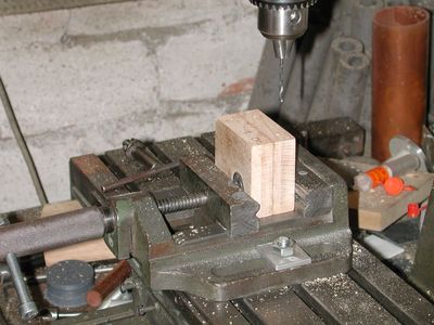
The mounting holes for both bearing blocks are drilled on the milling machine.
This way they will be in the same relative positions and the shaft will be exactly parallel to the base plate.
The bores for the ball bearings were made the same way, also to ensure precision.
Guess what? It actually worked as planned. Sometimes experience with these things comes in handy :-)
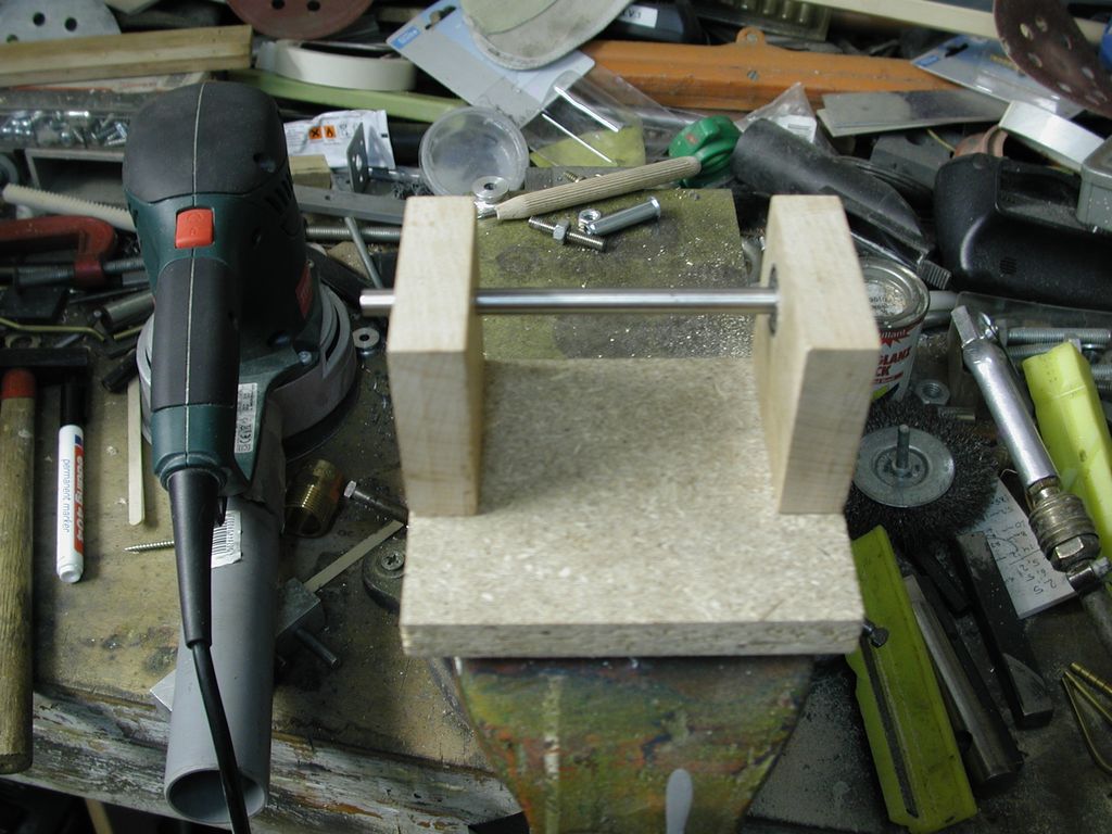
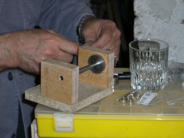
In the next phases we insert the shaft to the bearings and mount the bearing blocks on the base plate. The base plate is simple flake board since that was available on that particularsaturday evening. After mounting the bearing blocks the gears and the sprocket for the chain can be mounted.
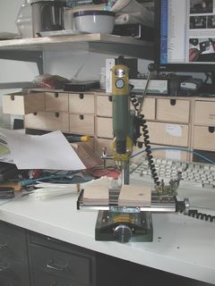
I made a holder for the motor on my Proxxon, which looks a bit like the little brother of the machine in Matthias' workshop.
Mine is well suited for working on PCBs, drilling and milling alike, and for small objects made from metal or wood.
And it better fits on my desk.
But this motor holder turned out to be too flimsical to actually hold the motor. The torque transferred from the motor to the drive shaft was a bit high.
So we had to make another holder.
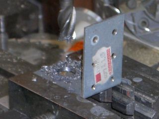
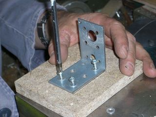
Luckily a cheap bracket - the type usually used in construction – was lying around.
And with a little modification it would accomodate the motor.
For my taste the faceplate of the motor (or gearbox in this case) was a strange construction with one mounting hole extremely close to the bearing of the drive shaft.
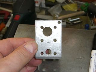
Well, this works.
And can be mounted easily on the base plate.
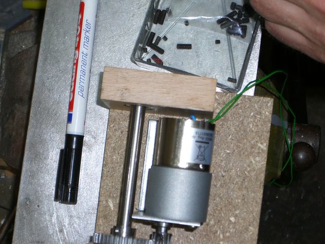
And after that the motor can be screwed to the motor holder.
After that the bearing blocks with the drive shaft could be mounted again.
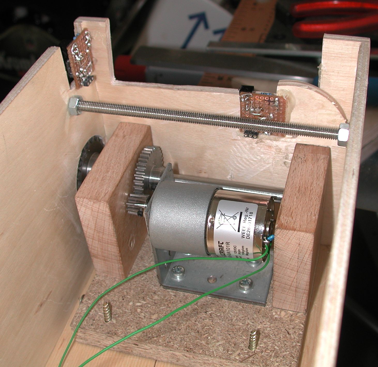
This pretty much completed the drive unit.
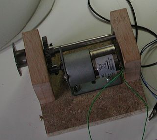
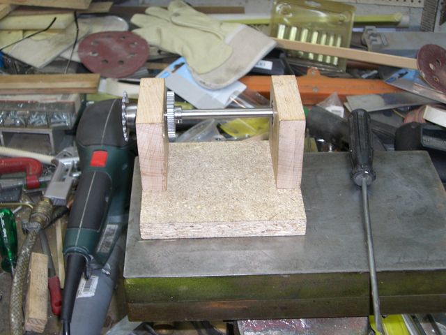
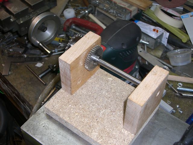
Another picture of the assembled drive unit.
Simple, huh? Actually, I left out some of the fun parts.
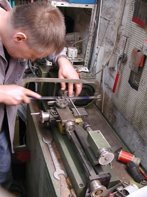
When shopping for the axle/shaft material, I was looking for 8mm diameter solid steel. Out of stock. Of course. So I went for a steel tube with 8mm nominal outer diameter, which turned out to be 8.05mm actual. Good thing we had a lathe available. Cutting the tube was a snap and using proper tools it was also fairly simple to enlarge the bore in the gear from 6mm to 8mm.
My original plan was to weld the sprocket and the gear to the shaft. I thought that would be fast and give us a very solid connection. Matthias advised against welding to the thin-walled tube, so we ended up drilling holes into the tube and the hub of the sprocket (the gear already had a bore with thread) and secure the gear and sprocket with screws. Not as quick and not as dirty as welding but definitely as solid.
Drilling into round objects like hubs of sprockets or driveshafts is quite tricky. Without a centre drill (Zentrierbohrer in german) and a precise drilling machine it is just a roulette game. Did I say that I am always jealous of Matthias' workshop when I am in there? :-) You never heard of a centre drill? In this Picture there is one on the right.
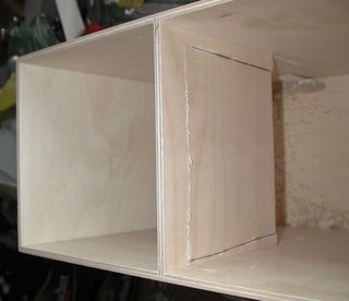
Now the drawer had to be modified.
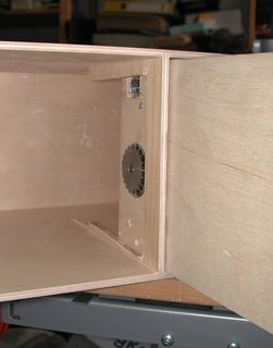
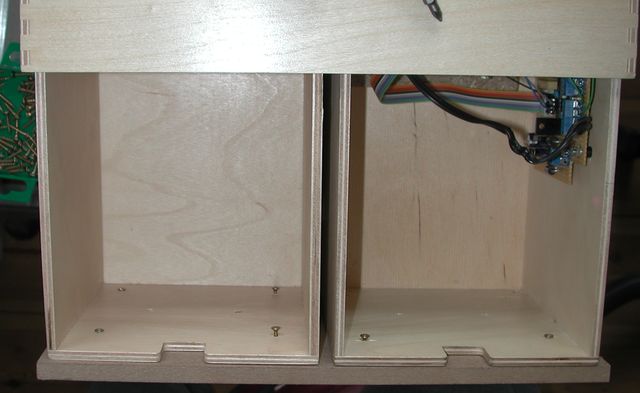
The drive unit is mounted inside the drawer with the sprocket outside.
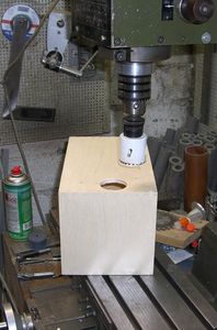
Making a big hole in wood is simple – with the right tools.

After some more modifications to the drawer, the drive unit is mounted inside.
The bottom of the drawer has elongated holes for this purpose, so the drive unit can slide a little to the left and to the right.
This way I could slide in the drawer with the sprocket all inside the drawer, then slide the drive unit to the left and bring the sprocket outside.
In this position the drive unit is screwed on with two screws through the left wall of the drawer.
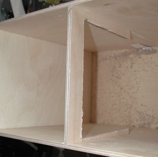
The corpus had to be modified slightly to accomodate the drawer drive.
Free-hand cutting is sufficient here, since the cuts will never be seen :-)
Proper tools like the Fein Multimaster are helpful in such endeavours, of course.
Remember: nothing is as expensive as cheap tools.
Fitting it all together
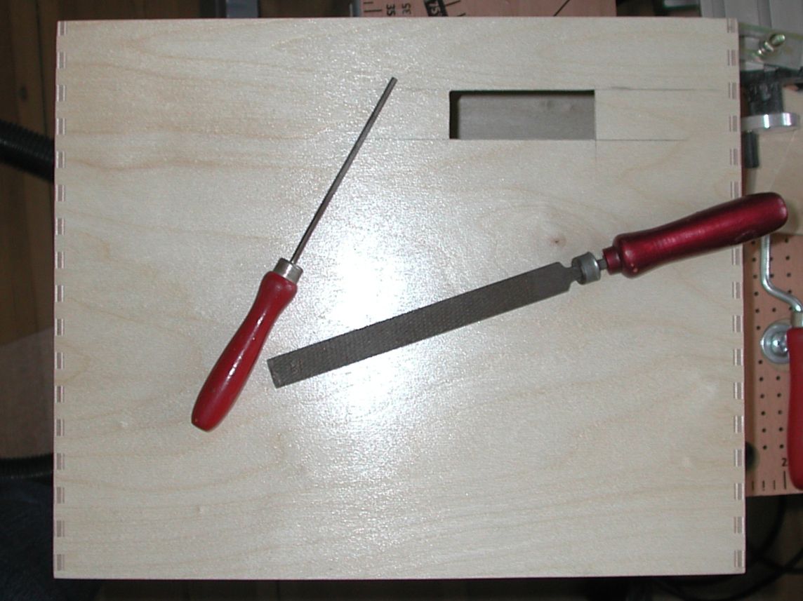
The corpus needed some more modifications: A display and a rotary dial needed a place to live.
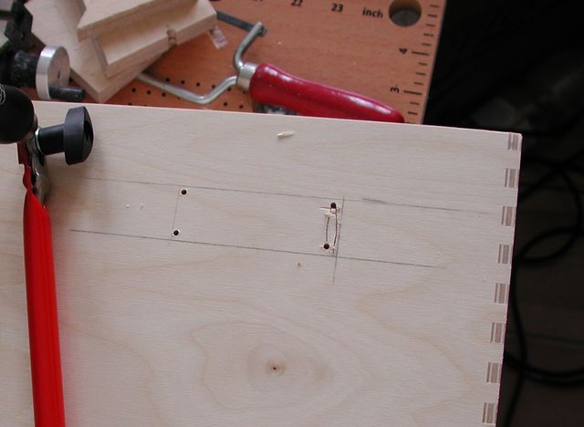
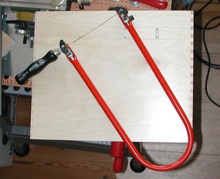
Many people mistake a fretsaw for a childrens toy. Many fretsaw kits are sold as a toy with happy children in the advertising. The ads never show the pictures of children that just have cut their fingers for some reason.
The fretsaw is not a childs toy, it is a serious tool – if you buy the right kind. The right kind is the kind where the arc can hold tension for more that 10 hours (though every arc will eventually fail if you neglect to loosen the blade after working with the saw) and where the blade holder is precisely parallel.
Mine is the intermediate type: not from the childrens toy set but also not really precise.
The two rasps (the flat is actually a file/rasp combination) on the other hand are from a fretsaw kit I got as a birthday gift at age 12, so they are almost 30 years old now. Still working. And good enough for making a display cut-out in the corpus of our Ikea Mackis here.
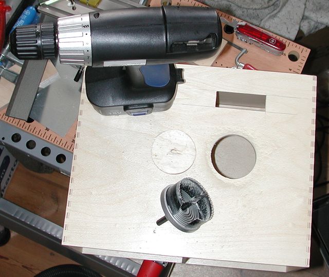
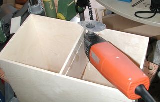
The hole for the rotary dial was a job for a power tool again.
My hole-saw kit is not the professional type that Matthias has in his toolbox, but sufficient to cut though 5.6mm plywood (the while hole-saw we saw above can handle steel, not only wood).
The free-hand positioning without any drawing or measurement turned out to be – äh – suboptimal later on. As usual.
Still it worked, and that is what counts, right?
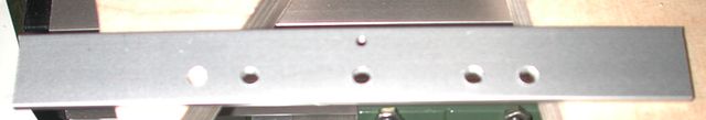
To attach the chain to the wooden corpus I designed a metal crossbar that would take the pressure from the chain and apply it to the wood one a larger area.
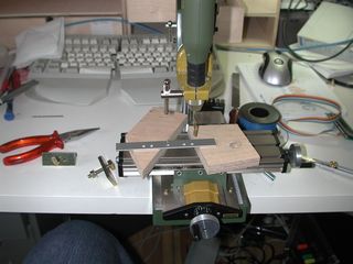
For pieces like this the small Proxxon is well suited.
The crossbar is actually needed becaus the wire that would fit through the chain is so small, it would have cut itself out of the wood. The aluminium crossbar can withstand the pressure much better.
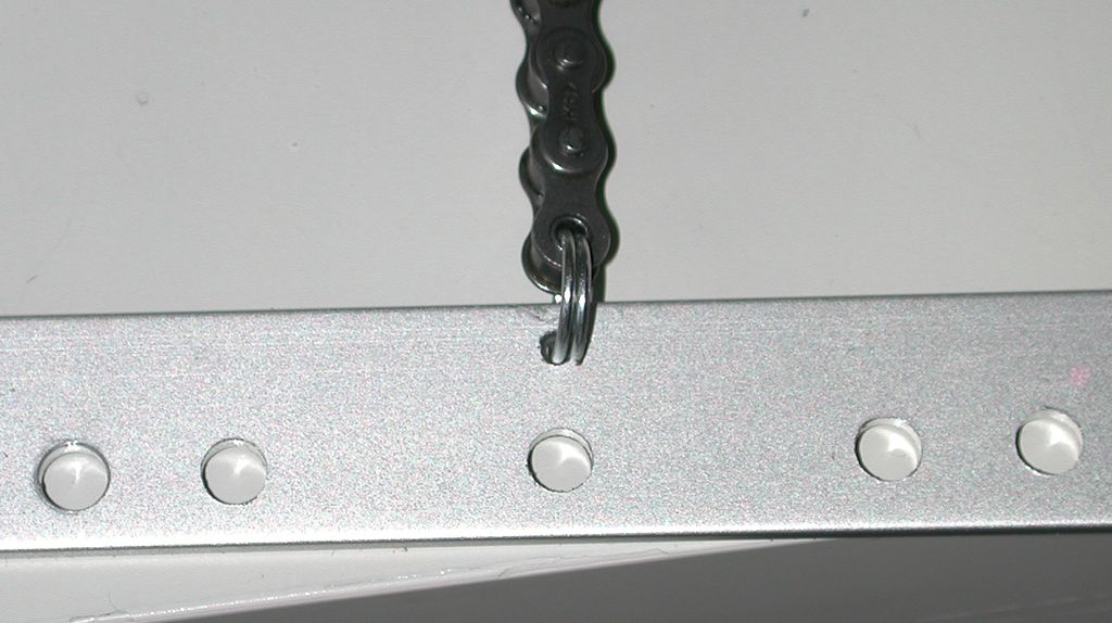
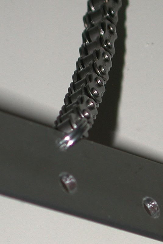
When testing the opening mechnism later on, it would tun out that the crossbar could well take the load, but the steel wire attachin the chain to the crossbar could not :-) The wire you see is one round cut from a spring. It forms something resembling a keyring.
When that broke later in testing, I replaced it with another pice of the same spring but this time soldered the ends together. This prevented bending open the ring. Btw: chain mail nowadays comes in two variants: the rings are just bent with the ends facing one another and the variant where the ends are brazed/welded together. The brazed version has protective quality, the other is just for show - even though there are historical examples preserved made just like it; they were probably just for show as well.
Maybe I should have soldered the thing shut right here.
I will know better next time – if there is a next time.
Using keyrings to attach things is a technique I picked up from the designer of our booth at CeBIT once. She did not want to nail down the exibits nor put everything behind glass, some stuff just needs to be available for touching, feeling and fiddling. So she attached metal chains to some exibits using ordinary keyrings. That would not stop a determined thief, but the hurdle proved to be high enough to get through all 10 days without losses.
Yes, CeBIT used to be 10 days long sometime in the ancient history :-)
Ok, back to the contraption at hand.
The crossbar is attached to the wooden corpus of the Mackis furniture using the usual method. The usual method involves Nylon cable ties. Works very well.
Of course this is well calculated and well engineered: the Nylon surface forms a perfect slide bearing for the drawer. Its not a bug, its a feature!
At this point the tests of the drive mechanics look very promising.
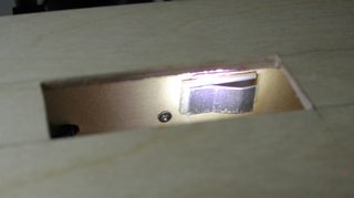
While the box is lying in this orientation, the maximum opening force the drive can create is limited. Only two teeth of the sprocket are in contact with the chain rollers at some points, so the chain slips a little. Once the box is in it designated position, the chain will go 180° around the sprocket, so the chain should no slip any more.
Opening and closing (with my thumbs replacing the gavity) works quite well at this point. hase is pleased!
The cables sticking out behind the drawer are a bit of a problem: they cause the drawer not to close all the way – just enough for the end-switch not to trigger, it seems. But at first I did not notice the actual reason, I just assumed the end-switch is not susceptible enough.
An adjustable reflector for the end-switch would solve that problem, I thought. This is glued in with hotmelt glue.
A glue gun is a really useful tool :-)
But the moving cables turned out to be the real problem.
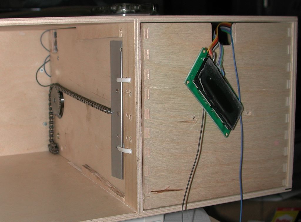
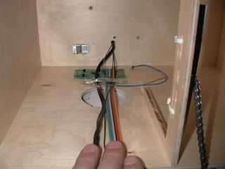
A cable guide glued to the corpus fixes that.
With this cable guide in place, the cables curl up inside the drawer when the box opens.
The flat ribbon cable is the display cable, we have seen in electronics.
The thin black, blue and grey cables come from the 3-position switch in the lamp.
The black cable brings power to the lamps.
Variable power from the controller board of course. Wow, everything works like a charm so far. hase is still pleased.
Testing and final assembly
At this point, the rotary dial and the display are not glued in to ease access to the innards of the box.
But I guess it is time to apply the finishing touches. Gluing in the display reveals that it was a bit short-sighted to position the display based on aesthetic properties only. In this position it is in conflict with the drawer – of course. Murphy at work.
Well, 5 minutes with rasp and file fix that, the cutout in the back of the drawer is now a bit larger.
Everything else works quite well and the videos showing the opening and closing are created in this phase. Still more than 24 hours to go until the wedding! Astounding!
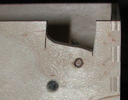
The closing video shows that at the end of the closing motion, the box suddenly drops about 1cm after it moved smoothly for like 10cm.
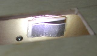
Inspecting the box from below while it is closing reveals the reason for this. When closing, the teeth of the sprocket do not go in between the rollers of the chain but on the chain links. If you have a bicycle with a chain-transmission (not a hub transmission), you can observe the same situation: while shifting from one sprocket to the next, the chain is in between the sprockets and slightly above the teeth.
That is exactly what happened here, because the sprocket was not protruding from the drawer enough :-(
Now, if you closely inspect the picture of the drive unit, you will see a screw on the left. The purpose of this screw is to limit how far the sprockets protudes from the drawer. Once the drive unit is mounted in the drawer, this can not be adjusted any more. Not at all. I tried.
So I was facing a point where I would have to dismantle the entire thing to get access to this adjustment screw. Bummer-squared! That or botch it. I went for the botch job solution first – and it worked. A second screw through the wall of the drawer into the bearing block for the shaft (thank god we made that from wood, not steel...) brought the sprocket out a little more – jsut enough to ensure the chain gos on to the sprocket as it should. Phew!
It is Thursday afternoon (well, night actually) and the wedding is on Saturday. A full Friday left to finish. Plenty of time left – and that is definitely a first in the chain of hase-wedding-present projects.
Attaching a base
Friday morning it is time to mount the whole thing on a base plate and with both drawers. At this moment, a potential employer calls and asks, if I could come by quickly for a job interwiev a little later that day.
Hmm. What do you answer there? „No, sorry, have to contsruct a wedding present for tomorrow.“ seems a little – äh – arrogant. „Sure sir, when exactly“ seemed more appropriate. And also made the project more real-life: „plenty of time left to finish“ is just not real life.
Still some time left. Lets finish this „real quick“.
No time left to go shopping for a base plate. What do we have in stock? Some MDF is available, that will have to do. Not the metal base I was shooting for, but still ok.
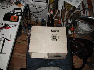
So I screwed the left drawer (the right one is the drawer with the drive unit) to the bottom plate and inserted that to the corpus.
Again, experience helped: before screwing on the other drawer, I did a „final test“ of the mechanism. Opening does not work. I solved the riddle, the display shows „richtig!“ and immediately assumes the box is open – no movement at all. Hmm. Software problem?
Actually, the end-swtich was too susceptible: the wall of the left drawer was reflecting enough light back to the end-switch that the switch was triggered all the time.
A quick cut into the left drawers wall fixes that. No time to make a nice, rectangular cut-out. This one also fits the bill („a hole – that is all I need“) and takes less valuable time to complete .-)
because both drawers have the same relative positions all the time, the cut-out does not need to be larger.

The the base plate is screwed on.
From the inside. Naturally.
And that is not really easy, since the whole contraption opens only 18cm or so.
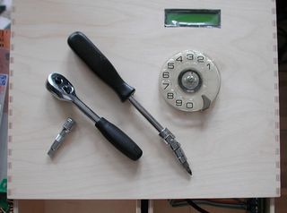
Again: proper tools make for good results.
Thanks for cardan joints and thanks for ratchet tools!
If you look a the picture closely, you will see that I screwed on the base plate completely skewed. Oh man! I was under pressure – still the job interview ahead of me.
hase was not pleased very much at this point :-)
Well, that type of mistake is easily fixed.
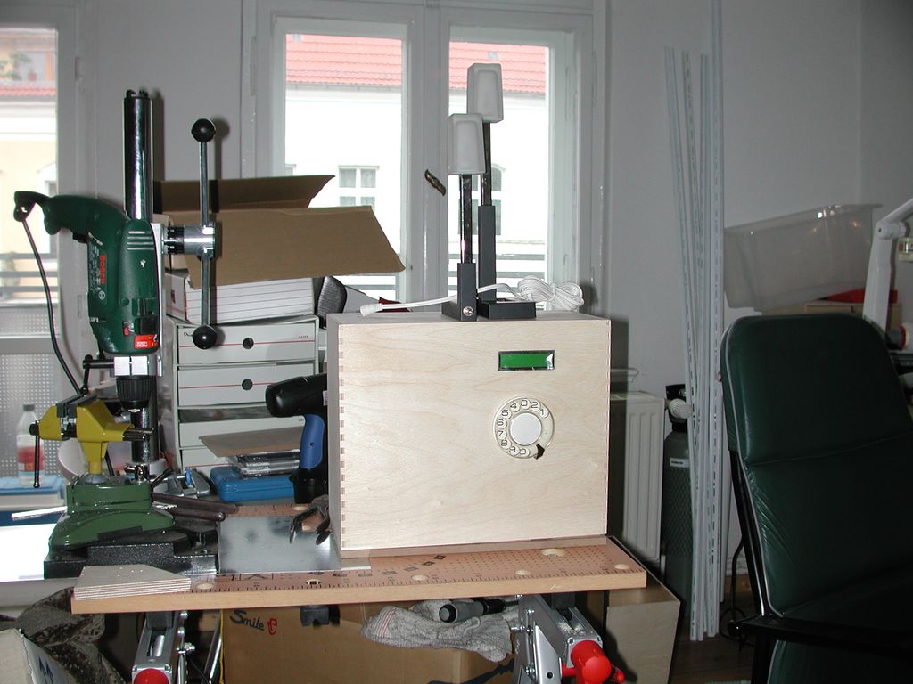
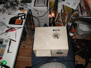
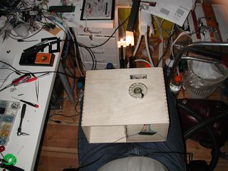
Still, it is finished.
And works. And looks cool – really retro even with the LC Display in there.
And it is useful – in away. It is a decorative lamp with dimmer. I should have incorporated a telephone, I think. Maybe the next one will be a telephone as well as a lamp :-)
And please do not tell me that my workshop – äh – office – äh – living room looks chaotic.
It does.
It is defined chaotic. It is supposed to be chaotic.
Its not a bug, its a ...