Electronics
Electronics is fun
even making it. Really! Beleive me! Even when it does look only tedious, error-prone and boring. Its fun! (if I keep repeating that to myself, I will start to beleive it again, I guess).
Actually, I have a lot of fun making something electronic, every time.
Constructing a wedding present
We have
- a rotary dial
- a 3-position switch
- an LC Display
all these are pretty much no-brainers. The LCD is a well-known thing and libraries exist to drive it. I used Peter Fleurys LCD-Library for the AVR-GCC. The LCD just needs 7 port pins to connect to the µC (Microcontroller). Solutions exist to use less pins by using port expanders but on a simple project like this one, we should have 7 pins available, right?
The rotary dial is basically two switches with one common pin. When you connect the common pin to ground and the two others to port pins on the µC, you are all set to decode the numbers dialled.
The 3-position switch that came with the lamp is connected in the same way as the rotary: the middle pin to ground, the two others to port pins, this way the µC can tell the position lfet-middle-right of the switch.
We also have
- a lamp
- a motor
that still need control.
The 12V/10W bulbs in the lamp will run on DC as well as AC (glow bulbs are so wonderfully simple. As simple as they are inefficient for making light :-). And when the DC is pulsed, we can easily control the brightness. So the lamps will be controlled by a PWM signal. The AVR Mega8 processor I am using on every project like this one will generate up to 3 different PWM signals in hardware, so that is easy. BTW: The Mega8 is a cousin of the Mega328 used in the Arduino that was invented after I had finished this project.
The lamps use considerably more power than a µC pin can provide, so we need some amplification. If you understand electronics, you may want to stop reading, becaus my solution is somewhat under-engineered. But I like it: it is simple, cheap and works quite well :-)
I simply drive the gate of an IRLIZ44N MOSFET from a processor pin. With the processor running from 5V this is enough to switch the transistor on and off and the processor pin can source and sink enough durrent to charge/discharge the gate fairly fast. At least at the low switching frequencies we use here.
Everything but the motor is covered now. All with solutions I had done or used before. A motor I had never driven from a µC myself. That is one of the reasons I wanted to use some electronics here, to learn about that.
Googling and researching a bit I found there is one standard solution to driving a motor that everybody-and-his-dog uses: The L293D chip includes the power transistors to drive motors up to 600 mA current consumption. My motor uses at most 300mA so we are on the safe side here.
The chip is pretty simple to use: 3 port pins drive the enable and the two direction inputs. When both direction inputs have different logic value, the motor turns, when they have the same value the motor is stopped (and acts as an electric brake). The enable can be driven by a PWM signal again to control rotational speed of the motor – perfect.
I am actually using the PWM to soft-start the motor (ramp up the voltage slowly). This makes the sound and motion appear very smooth, not jerky. I also use the PWM control to use less voltage when closing the box; this way opening (lifting) and closing (lowering) the box works at pretty much the same speed. Applying maximum voltage when closing makes the closing process visibly faster than opening – and that gives an underpowered look :-) Hey, thats engineering!
Lets heat up the soldering iron
Why is that thing called a soldering iron? There is no iron in there, right? Maybe iron was used in the middle ages or at times of the roman empire. Whatever.
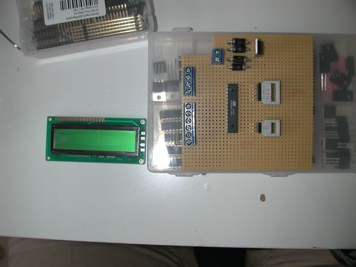
First order of business: place all the parts on the PCB to get an impression of the space required.
Looks fine to me.
„There is lots of space in this mall“ (Jake to Elwood)
We can not see the motor control IC here, because I did not have it in stock on the week-end when I started soldering :-)
Every appliance is only as good as its power supply.
Thoses wise words appeared in Elektor magazine in 1971 (I think). I learned of them as a frequent citation when I started working profesionally (i.e. getting paid for it) electronics in the mid-80ies of the last century.
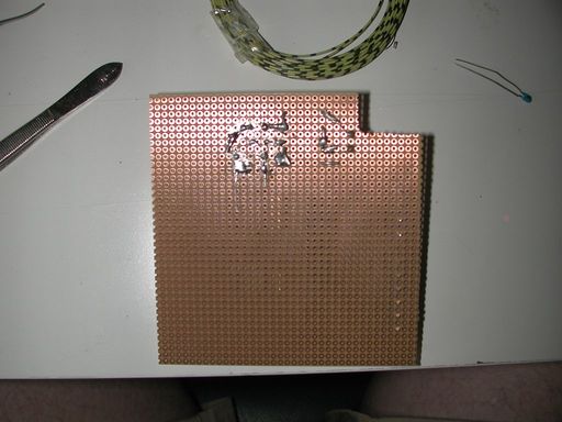
In order not to re-learn that again the hard way, I started with the power supply part of the controller board.
The SB360 diodes in the rectifier are choosen for a very good reason: I had them lying around. Other reasons might include low voltage drops (only 0.4V usually compared to the 0.7 for rectifier diodes) and the 3A maximum current. No other diode in my usual stock can handle 3 amperes. I only handle that kind of current in switching power regulators, and there a shottky is a must.
Wiring up the 6-pin header for flashing the firmware and the 10-pin header for the display is pretty straightforward.
Or it should be. But I managed to frack it up: I wired the ISP header mirrored. Not good.
I found the error (a good thing the programmers are so robust: nothing burnt out :-) and fixed it. At least I wanted to.
But somehow I managed to leave out the connection from processor ground to the power supply ground. That error was not apparent immediately: as long as the flash programmer was connected, the ground connection was made via the programmer and the USB to the computer. As a result he controller later worked with the programmer connected and did not work wit hhe programmer detached. It took me a full 3 hours to figure out that one – I am getting old :-(
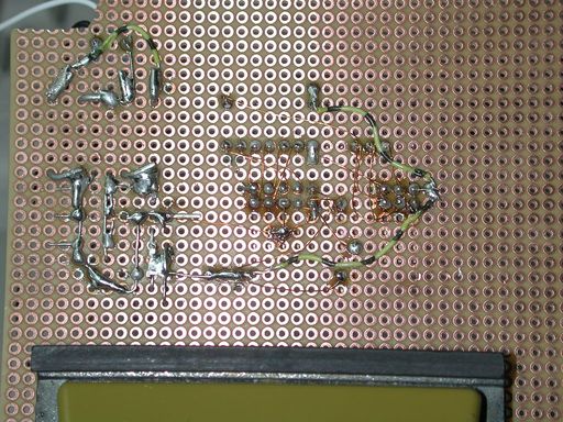
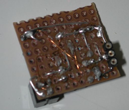
The type of wiring I use here is known as „Fädeln“ in german. The small copper-coloured wires are 0,2mm strong copper wires with an enamel insulation that can withstand about 60V. Therefore the wires may cross each other without forming a connection.
For a small circuit like this one this method is much faster than making a layout and etching a PCB. It also avoids messing with chemicals lile FE-III-Cloride. Debugging that stuff can be quite annoying, though.
The enamel insulation is supposed to melt and burn at 300°C, so the 370°C hot tip of the soldering iron should burn it right off, exposing the raw copper below. That copper the tin then bonds with forming a solder joint. But the stupid stuff does not know that and sometimes does not burn off – so the joint looks like it is soldered but the electrical connection is not there. Grummel.
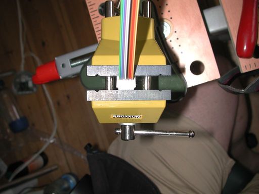
I love the crimp connectors. It is soo simple: Fiddle a piece of flat-ribbon cable in the opening between the bottom and top half of the connector, close the vice and all connections are made at the same time.
Unless you had the ribbon cable in there not properly aligned or not exactly orthogonal :-)
If you do this at home:
- check for short circuits after crimping.
- Practice.
- After the first 2000 crimp connection you will master it.
Well, I did after about 2000 crimps or so :-)
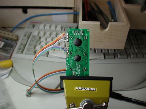
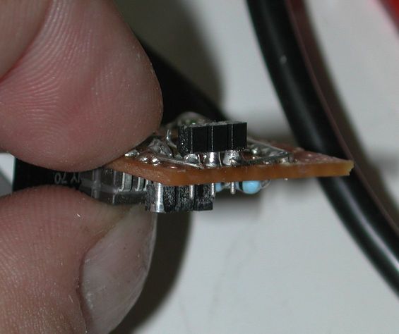
Soldering the 10 pins to the display takes so much longer than crimping the other side...
The two black blotches are PU-resin poured on the chips on the board. These chips are soldered to the board without an IC housing and then covered with PU.
This type of assembly is found only on stuff made in rather large quantities (like pocket calculators and LC displays).
I sometimes wonder, why it is not used more frequently.
Anyway.
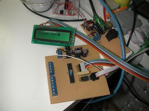
Once all joints are made, the mirrored pinout corrected and the missing ground wire is found and replaced...
... a first simple firmware can actually show „Erster Test“ on the display.
So this works.
Good.
End-Switches: Electronic or mechanic?
We will have limited-length linear motion on this project. We must limit the motion of the drawer, the motor must turn off at two points.
Reliably.
Or the whole thing will self-destruct.
Reliable sensors for the end positions are...
Well, there is a very good reason why the big CNC machines almost always use inductive end-switches. Mechanical switches are reliable. My mouse has two and they always work – unless I am targeting a boss mob in WoW for example. Mechanical microswitches are very reliable – unless used in one of my projects. They never work there.
I want something else this time.
Hmm, the CNY70 looks promising.
Basically it is an infrared LED and a phototransistor in one package. Both face up from the package, so the transistor detects light that is reflected back to it. This makes for a pretty nice proximity sensor for anything that reflects IR light.
The most simple appliction is to connect the IR-LED to a power source and the phototransistor to a processor port pin (with a pullup). I did not trust that to be reliable, because the signal would bounce hight/low if the drawer would move a little jerky. I needed hysteresis.
A Schmitt-Trigger provides that.

A complicated selection process led to the TL061C operational amplifier which would become the base for my Schmitt-Trigger. The selection process involved looking through multiple biscuit boxes full of left-over electronic parts from older projects. One box that has parts in there I did not use for like 20 years. There I found the 061 single-opamps :-)
Had I not found them, each end-switch would have ended up with a Schmitt-Trigger made from one quarter of an LM324 which is the usual opamp I am using for this kind of application.
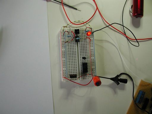
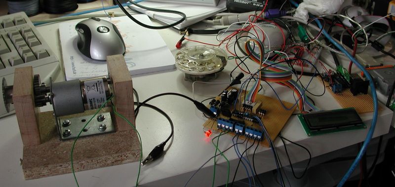
The breadboard setup pictured above allowed me to quickly experiment with different values for the resistors and see the effect.
This method of finding the right values for components for an application is frowned upon in the academic cicles all the time.
But I find it providing results faster by a factor of 10 compared to running simulations :-) (I never really became friends wiht SPICE. Nice program. Just never has the component models available that I'd need for meaningful simulation results).
Always remember the wise words my first boss told me when he found me using pen and paper to find the proper values for the feed-back resistors on an Opamp-based amplifier:
„The experiment is a well-accepted scientific method for gaining knowledge“
Or in other words: just try it. If smoke appears, try something else. :-) Äh: do not use this approach to anything that could harm other or you. But with simple low-voltage stuff...
The circuit above gives me an optical-end-switch with a pretty good sesitivity. It will trigger when the reflecting surface is about 5mm above the CNY70. The hysteresis is about 3mm: the signal will switch again when the reflecting surface has moved away to 8mm above the CNY70. Even if the drawer is vibrating when moving or the movement is a little jaggy, the vibration will not exceed 3mm for sure. The processor should see a very stable „destination has been reached, turn off motor“ signal.
So its time to move from breadboard experiments to PCBs.
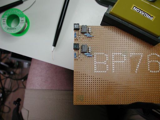
Since I need two end-switches, I make them at the same time.
Note the lead-free solder and the good old „Fädelstift“.
If you know a source for spare tips for the wiring pen, tell me about it, I could really use one.
These things are no longer produced, I think.
(Update: the other type (green plastic) of Fädelstift is still available, but outragously expensive nowadays.
And it suffers from the same problem: the plastic of the tips melts well below the 300°C needed to burn off the insulation from the wires.
One day at the lathe in my workshop provided me with a replacement tip for my old (black) wiring pen lovingly made from PTFE!
Still: there is visible wear on the tip :-<
And a metal tip would scratch the wires insulation, rendering the whole thing useless.
I no longer wonder why this method of making prototypes has gone out of style :-)
And when both are wired, they are cut out of the larger PCB.
The connector on the solder side of the PCB was an afterthought – a useful one :-)
Please note the lack of PCB space to put mounting holes or the like. There must be a reason why I always omit those on my quick-and-dirty projects.
Even the fairly large components used here can create some challenges for soldering. Placing the additional connector on the solder side even made me reach for a magnifier.
I did not use a microscope for soldering for a very simple reason: I do not have one. Stereoscopic microscopes with a mount that allows for working with tools uinder them do exist. I have seen them in an auction catalogue. I placed a bid on one when the Benq mobile phone fab in Germany went bankrupt. Even that one was too expensive for me :-)
Wiring it all up
with the controller board and end-switch modules finished it is time to wire it all up for the first time and see if the motor actually runs. And – surprise? - it does and creates exactly the right sound: audible but not too loud.
Firmware
Time to get started on the firmware. The firmware takes input from the rotary dial, controls the motor (stop, direction, speed), test for end-switch conditions and control the light (brightness).
The firmware also reads some values from the EEPROM in the processor and displays a riddle to be solved before the box opens for the first time. And while we are at the EEPROM anyway, it also remembers the last setting for the lamp brightness.
After solving the riddle the user can choose to enter a 6-digit pin. Once that is set, it can be used to open the box without entering the solution to the riddle. I admit: the PIN-feature I put in just for me, so I could test the mechanics without solving the riddle all the time :-)
I bet, SMD technology (you know: the stuff with the components you can hardly see if you are older than 40) was invented to allow for even smaller lab spaces :-)
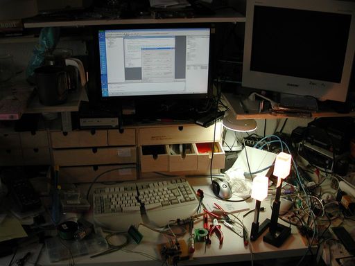
In the back the AVR Studio application is already open, GCC is primed and ready. My trusty ol' Cherry keyboard takes up some valuable space.
The dark spot between the two monitors is home to my Weller soldering iron and to the right in the back you see my lab power supply.
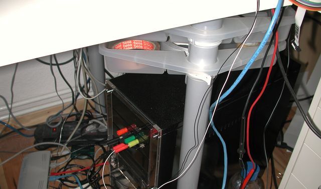
But most my experiments are powered from my PC. PC type power supplies provide very stable 5V and 12V with really high output (current-wise) and they are dirt-cheap. So my PC has outputs for 3,3V, 5V and 12V on the front panel. Comes in handy when experimenting with electronics :-)
The flimsy-looking black and white wires running up to the desk are actually powering the wedding-box-controller.
Features
Seems, all my programs for µC end up to be some state machine.
There must be a reason to that and it may be very interesting for some psychiatrist – but for me that is just the way I program :-)
Basically all µC programs are endless loops and my main loop typically has some code checking stuff (i.e. Flags from ISRs) and then goes into a switch(state) {}.
On powerup the firmware checks the 3-position-switch.
- In middle position, we are in idle state: stop motor, display „Ready“, load the last-remembered brightness value into the timer compare register and that is it.
- Switch in left position activates the dimmer function. In this state the display shows „Dimmer“ and the rotary dial becomes a 10-level dimmer. Level 0 switches off the lamp alltogether, level 9 is 100% power, the other are somewhere in between. The value is stored in EEPROM every time it is changed.
- The switch in the right position brings the firmware into motor control mode. This mode can be left only by entering something or poweroff. That is a feature, not a bug!
In motor control mode I first check if the riddle was solved before (a variable in EEPROM) and a PIN has been stored. In that case the display shows „PIN“ and the controller reads 6 digits. The box opens with the correct PIN. If the riddle was never solved, the Display shows „Zauberwort“ and a blinking cursor in the second line. Now the user must enter the solution (which is „SESAM“, the german equivalent of „SESAME“ as in „Sesam öffne Dich“ or „open sesame“).
This is done by entering letters with the rotary dial.
A mobile phone came in handy for the bride and groom when they tried to figure it out: the number-to-letter mapping is written on the keypad.
I had a really good time watching them fiddling with my contraption :-)
(Edit: I probably must add: this whole project was made before smartphones became all the rage :-)
The digits 2 to 9 produce the usual letters we all know from entering SMS messages without the T9 dictionary.
The digits 1 and 0 move the cursor one position forward or backward respectively.
Once the user has figured out to dial „77771331777712161“ the diplay shows „richtig!“ and one second later the motor starts.
The motor is started with approximately 50% duty cycle on the PWM, the cycle is increased a bit every 2 microseconds.
That creates a nice soft start and the movement ramping up to full speed.
The motor is run until the end-switch for „open“ triggers or a timeout is reached.
The timeout is really important: I had the end-swtich disconnected on one test and without the timeout, the motor would have done something very destructive.
Once the box is open, the user is kindly asked to place the 3-position switch in the middle position again. That triggers the closing.
Again the motor is run starting at 50% duty cycle and ramping up to about 86%, so the motor gets less power on closing. That makes it run about the same speed as in the opening cycle.
Again this runs until the end-switch fires or a timeout is reached.
There we are: we have a little computer to control the mechanics of the box.