Nein, wirklich!
Ja, ich bin immer noch Ingenieur. Und mach auch professionell mit Mikrcontrollern rum, in der Tat.
Und trotzdem mag ich Arduino. Für dieses wunderbare Gemisch an total genialem Zeug und dem unglaublich entsetzlichen Grütz, der in diesem Umfeld zu finden ist. Das komplette Spektrum vom Bastler bis zum Konstrukteur ist abgedeckt und irgendwie kommen alle miteinander klar. Klasse!
Und Nervig. Immer wieder nervig, wenn eben wieder mal man an der „alles Grütz!“ Stelle angelangt ist.
And here we have to switch to English - to broaden the audience a little.
I am working on a little project. This involves a user interface containing rotary encoders and pushbuttons. Very much standard.
I have used such things before and used the standard techniques.
But usually I am developing my µC stuff in C on bare metal without the abstractions provided by Arduino or suchlike.
 For example, the transmitter for the recent bithday present I made for a friend, uses two rotary encoders and their pushbuttons.
The present was a floor lamp with a head containing two LEDs (a 50W cool-white and a 20W yellow, each on an old Athlon-cooler) driven by a PWM dimemr I reused from an older project.
The dimmer uses a serial bus to receive the PWM duty cycle for each of the 8 channels, so I had to make a transmitter to send brightness values on two channels.
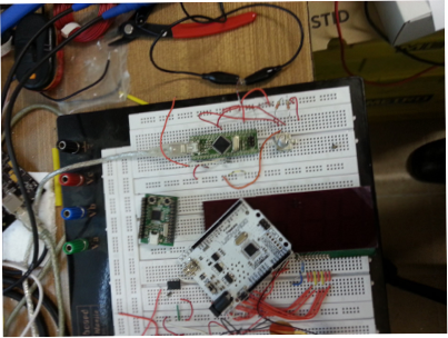
It is a simple board, just a few wires, so I made it by hand or perfboard.
For example, the transmitter for the recent bithday present I made for a friend, uses two rotary encoders and their pushbuttons.
The present was a floor lamp with a head containing two LEDs (a 50W cool-white and a 20W yellow, each on an old Athlon-cooler) driven by a PWM dimemr I reused from an older project.
The dimmer uses a serial bus to receive the PWM duty cycle for each of the 8 channels, so I had to make a transmitter to send brightness values on two channels.
It is a simple board, just a few wires, so I made it by hand or perfboard.
My old rotary encoder routinge is working well. It is robust and stable as hell, as is the key debouncer logic.
The reason for this stability: I used somebody elses idea :-) Peter Dannegger is a regular contributor to the forums at www.mikrocontroller.net. And he is a genius. Really: the stuff he posts is hard as granite to understand. And once you got the concept, there is no way in hell to improve on it - pure genius.
His key debounce and his rotary encoder logic is of such kind.
Some of my readers may need some explanation. The concept of „bounce“ is pretty simple: when you push a button, the electrical contact is not established immediately, but hte contact closes, opens again, closes again and so on for a little while. The little while is somwhere between a few microseconds (millionths of a second) to a few milliseconds. It really depends on the switch. This is bad. Well, actually, it just is, but when you do not prepare your program to deal with it, it can be really bad. Connect a bouncing contact to an interrupt line of a processor, and you will have all kinds of „fun“ debuggin why the fracking thing is working sometimes, and not on others. Debounce!
Debouncing pushbuttons is a very common requirement. so you should expect a standard solution to be present in the Arduino environment: that would really help beginners to avoid this trap. There is none.
Actually, it is worse. The Arduino environment has no standard debounce, but there is an example sketch on the issue. Older version of the example sketch used the worst possible method. Literally worst practice. The current example is - well - not as bad. The general principle is ok, it does not block program execution for the entire debounce time any more.
Maybe, the italians did that one on purpose: let beginners learn their lesson about debouncing, so they will not assume a switch to just close or open. Maybe.
But could you guys just have used one of the accepted solutions that are around for decades? My implementation you will find below.
Roraty encoders are another issue. They are around for some while and they are useful in two places: - measure rotation (duh!) of a motor-driven axle - user input using rotating knobs. The two applications have different requirements. Rotary encoders attached to a motor are used either to measure the rotation speed (for controlling that) or to measure, how far the spindle has traveled. In the first case, a missed transition is not really bad, in the latter you must not miss a single step of the encoder, or your measurement of the position will be off. See? Different requirenemts right there.
Human-turned knobs to input a value like „volume“ or „brightness“ are another matter: missing a step is not a problem there (the person will simply compensate) andthe pulses are also pretty slow.
Again: Peters implementation is excellent for the human-input type; I do not trust any measurements on my CNC machines to the algorithm yet, but for a brightness-knob it is perfect.
So here is my solution, which works ok on the Arduino Leonardo and the Leo-alikes; this category includes pretty much any board containing an Atmega32u4, I am using an U4DIL from Reusch for my experiments at the moment.
This is not an Arduino library. Because you have no access to the timer interrupts as log as you stay within the Arduino-happy-place. Instead, it is a modification of wiring.c which is part of the Arduino core (the code that gets attached to everything you write and provides the standard Arduino environment with digitalRead/digitalWrite, analogRead and so on).
If you install this, it will be overwritten the next time you update your IDE. If you have an idea how to better incorporate it to the Arduino environment: drop me a note at hase@hase.net
The logic is explained in the comments in the file, so I just give a short sketch here. And an apology: the key-debounce uses switches to ground and pullup (i.e. the internal pullup in the AVR), the encoder uses the common pin on +Vcc and pulldown resistors on the encoder phases. I will change this „real soon now“ :-)
My implementation uses Port D for the key input; not all Arduino versions provide access to all pins of Port D and if the hardware serial is in use, this will also cost you 2 pins. Change it to Port B or C if you feel the need.
The key debounce is a counter. It counts to 3 (0..3, 2 bit). Each key has its own counter of two bits. The two bits are in different variables in RAM (unsigned char ct0 and ct1). The trick is, to read an entire 8bit port of the AVR and use bit-operatins between the two counter bytes and the two bytes containing the current key states and key-change-indicators to create the 8 counters of two bits each. This results in a very compact and efficient code. And it debounces 8 keys with a single routine. Äh, you do not use 8 keys in your project? Well, in that case just ignore the bits in key_state that you do not need - thats it! And then folic when you add another key and the timing of your program changes not a single bit: the debounce stays exactly the same.
So: the port is read, compared with the current state and - if the state in the port is different than the current key_state (debounced), the counter is incremented - if the state is the same as the one in key_state, the counter is reset Result: if the input shows a change 4 times in a row, the counter rolls over: in this case the new state is stored in key_state. The timer is running at a prescaler of 64 in Arduino, resulting in 1.024 ms between runs of the ISR. So if the key input is stable for 4,096ms, the debounced state changes. Pretty solid, but make sure, the 4ms is long enough for the switch you use. My typical pushbutton bounces in the µs area - so this is actually overkill. But mechanical rrelais are known to need longer debounce times.
The encoder part is also pretty neat. It treats the output of the encoder as a 2-bit integer encoded in gray code. The gray code is converted to binary, shifted to the value range -1..1 and added to the encN_delta variable. This way the ISR keeps track of rotation. The main loop simply adds this signed value to a variable representing the current position and then resets it to zero. BTW: this part of the implementation is bound to loose some impulses every now and then, because the ISR might change the delta value in between the add and the zero value. Blocking interrupts during this time may help, but will screw up the ISR timing a little. For a human-rotated knob, this is still fine :-)
The encoders are connected to Port F in my implmentation, change this to other ports for chips without an F. The Atmega32u4 has 6 pins on F, so we can read 3 encoders here. If you use less than 3, it may help to remove teh superflous code from the ISR to free up som CPU cycles.
Well, enough of all that, here it is. Applications/Arduino.app/Contents/Resources/Java/hardware/arduino/cores/arduino/wiring.c
        /*
          wiring.c - Partial implementation of the Wiring API for the ATmega8.
          Part of Arduino - http://www.arduino.cc/

          Copyright (c) 2005-2006 David A. Mellis

          This library is free software; you can redistribute it and/or
          modify it under the terms of the GNU Lesser General Public
          License as published by the Free Software Foundation; either
          version 2.1 of the License, or (at your option) any later version.

          This library is distributed in the hope that it will be useful,
          but WITHOUT ANY WARRANTY; without even the implied warranty of
          MERCHANTABILITY or FITNESS FOR A PARTICULAR PURPOSE.  See the GNU
          Lesser General Public License for more details.

          You should have received a copy of the GNU Lesser General
          Public License along with this library; if not, write to the
          Free Software Foundation, Inc., 59 Temple Place, Suite 330,
          Boston, MA  02111-1307  USA

          $Id$
        */

        /* added by hase:
        - reading port D with debounce: up to 8 Buttons
        - reading port F as 3 rotary encoders

          reading a port should be harmless even when it is configured
          as output or alternate function (such as PWM): the data
          read will be bogus, but the function of the port is undisturbed.

          the algorithmy here are by Peter Dannergger, published
          in the mikrocontroller.net forum (german).

          The key debounce is pretty neat:
          three bytes in RAM are used. One byte stores the "current debounced state" of each key.
          Two more bytes are used for the debouncing like this:
          Each bit position in both bytes is used for one input so
          button/key 0 is tracked in the LSB of each byte and key 7 is tracked in the MSB of each byte.
          The two bits for each key form a counter; this can count from 0 to 3.

          If the value read from the port is different from the last value red, the counter
          (for this key) is reset.
          If the current sample and last sample are the same, the counter is incremented
          The overflow of the counter is stored in the current debounced state.

          The effect is:
          - if the key was read in the same state 4 times in a row, this state is stored.
          - bouncing will reset the counter.

        We are running in the normal Arduino Timer0 here.
        This means we take one sample roughly every millisecond (actually: 976,5625
        sample per second).
        So we consider a switch value valid if it is stable for approx. 4ms.
        In my experience, this is pretty safe, my typical buttons bounce in the <1ms range.

        The cool thing about Peters algorithm is: debouncing one or 8 buttons takes _exactly_
        the same amount of CPU power.

        If you try to understand the logic, it is a bit hard: this is desigend to work with
        Pull-Up resistors and the buttons connecting to GND: the LOW value (read
        as digital 0) is teh "active" value.

        To use the key states in the main loop, you simply read the variable key_state.

        The other algorithm - also by Peter Dannegger - is used to read rotary encoders.
        A lot of theory exists about encoders, how to read them efficiently, how to use
        Interrupts or Pin-Change-Interrups and such.
        I found this one to be universal, stable against bouncing and lightweight.

        The ISR counts the rotary pulses and stores them in one signed variable per encoder.

        To use this, you simply add this value to a variable in the main loop and then zero it.

        This method has the risk of loosing some pulses: if the encoder-increment changes before being zeroed.
        I use this for manual rotary encoders like volume dials, and there ist is not a problem.

        The theory behind this one is pretty simple again.

        If you look at the 2-Bit-Value output by a rotary encoder, you will see it is
        actually a 2-bit gray code
        0  -  1 -  2 -  3
        00 - 01 - 11 - 10

        This we convert into binary

        gray bin
        00   00 : no conversion
        01   01 : no conversion
        11   10 : convert
        10   11 : convert

        as we can see, the conversion is simply: if the MSB is st, invert the LSB.
        The MSB is encoder phase B, the LSB is encoder phase A, so the code
        if (PHASE_B)
           i ^3
        does the conversion.

        And then we compare with the readout from the last time the timer ran
        i -= enc_last


        now the value is debounced: gray code only changes in increments of one, so an increment of 2
        is an error and ignored:
          if( i & 1 ){
            enc_last += i;

        All changes are now either 0b01 (one step forward) or 0b11 (one step backward).
        This we can use to change the current count of the encoder:

        enc_delta += (i&2)-1;

        Some notes about communication between a main loop and an ISR

        By defining a variable "volatile", we tell GCC: read this from memory every time it is needed: it may have changed.

        This allows for changing hte value of the vatiable from different places in the code.

        One source file must declare the variable (as usual: all variable must be declared), the other then references to this variable using the "extern" keyword.
        the "extern" tells GCC to look for a variable of the same name declared elsewhere.

        */

        /* Arduino Leonardo port mappings:
        Port F: Analog in.
        PINF0: Ain5
        PINF1: Ain4
        PINF4: Ain3
        PINF5: Ain2
        PINF6: Ain1
        PINF7: Ain0

        The pins f2 and f3 do not exist on an Atmega32u4? Well...

        Port D: mostly digital and PWM:
        PIND0: digital 3, pwm
        PIND1: digital 2
        PIND2: digital 0, RX of hardware serial
        PIND3: digital 1, TX of hardware serial
        PIND4: digital 4
        PIND5: txled (not a pin on Leonardo)
        PIND6: digital 12
        PIND7: digital 6, pwm

        */

        #define KEY_IN PIND // read port D as key input
        unsigned char key_state; // stores teh debounced key state, inverted
        unsigned char key_press; // indicates a key press was detected

        // Port F is used for the encoders
        // The encoder code works with any port pin. It is possible to connect each phase to a different port, if necessary
        #define enc0_phase_a (PINF & (1<<PINF0))
        #define enc0_phase_b (PINF & (1<<PINF1))
        #define enc1_phase_a (PINF & (1<<PINF4))
        #define enc1_phase_b (PINF & (1<<PINF5))
        #define enc2_phase_a (PINF & (1<<PINF6))
        #define enc2_phase_b (PINF & (1<<PINF7))

        volatile signed char enc0_delta;
        volatile signed char enc1_delta;
        volatile signed char enc2_delta;


        #include "wiring_private.h"

        // the prescaler is set so that timer0 ticks every 64 clock cycles, and the
        // the overflow handler is called every 256 ticks.
        #define MICROSECONDS_PER_TIMER0_OVERFLOW (clockCyclesToMicroseconds(64 * 256))

        // the whole number of milliseconds per timer0 overflow
        #define MILLIS_INC (MICROSECONDS_PER_TIMER0_OVERFLOW / 1000)

        // the fractional number of milliseconds per timer0 overflow. we shift right
        // by three to fit these numbers into a byte. (for the clock speeds we care
        // about - 8 and 16 MHz - this doesn't lose precision.)
        #define FRACT_INC ((MICROSECONDS_PER_TIMER0_OVERFLOW % 1000) >> 3)
        #define FRACT_MAX (1000 >> 3)

        volatile unsigned long timer0_overflow_count = 0;
        volatile unsigned long timer0_millis = 0;
        static unsigned char timer0_fract = 0;

        #if defined(__AVR_ATtiny24__) || defined(__AVR_ATtiny44__) || defined(__AVR_ATtiny84__)
        SIGNAL(TIM0_OVF_vect)
        #else
        SIGNAL(TIMER0_OVF_vect)
        #endif
        {
        // copy these to local variables so they can be stored in registers
        // (volatile variables must be read from memory on every access)
        unsigned long m = timer0_millis;
        unsigned char f = timer0_fract;

        m += MILLIS_INC;
        f += FRACT_INC;
        if (f >= FRACT_MAX) {
        f -= FRACT_MAX;
        m += 1;
        }

        timer0_fract = f;
        timer0_millis = m;
        timer0_overflow_count++;

        /* additions to read and debounce keys and to read rotary encoders
        hase 10-Feb-2013
        */
        // Variables for the encoders
           char i = 0;
          static signed char enc0_last = 0x01;
          static signed char enc1_last = 0x01;
          static signed char enc2_last = 0x01;

        // Variables for the key-debounce
          static unsigned char ct0;
          static unsigned char ct1;
          unsigned char j;

        if (enc0_phase_a) {i=1;};
        if (enc0_phase_b) {i^=3;}; // converts gray code to binary

        i -= enc0_last; // difference to value from last ISR run

        if (i & 1) {
           enc0_last += i;
           enc0_delta += (i&2) -1;
           }
        i = 0;

        if (enc1_phase_a) i=1;
        if (enc1_phase_b) i^=3; // converts gray code to binary

        i -= enc1_last; // difference to value from last ISR run

        if (i & 1) {
           enc1_last += i;
           enc1_delta += (i&2) -1;
           }
        i = 0;

        if (enc2_phase_a) i=1;
        if (enc2_phase_b) i^=3; // converts gray code to binary

        i -= enc2_last; // difference to value from last ISR run

        if (i & 1) {
           enc2_last += i;
           enc2_delta += (i&2) -1;
           }

        /* and now for the key input and debounce */
          j = key_state ^ ~KEY_IN; // ckeck: did a key change?
          ct0 = ~( ct0 & j);  // this and the next line increments the counter or resets it
          ct1 = ct0 ^ (ct1 & j);
          j &= ct0 & ct1; // check rollover
          key_state ^= j; // change key state if the counter rolled over
          key_press |= key_state & j; // this signals a key-press to the main loop

        }

        unsigned long millis()
        {
        unsigned long m;
        uint8_t oldSREG = SREG;

        // disable interrupts while we read timer0_millis or we might get an
        // inconsistent value (e.g. in the middle of a write to timer0_millis)
        cli();
        m = timer0_millis;
        SREG = oldSREG;

        return m;
        }

        unsigned long micros() {
        unsigned long m;
        uint8_t oldSREG = SREG, t;

        cli();
        m = timer0_overflow_count;
        #if defined(TCNT0)
        t = TCNT0;
        #elif defined(TCNT0L)
        t = TCNT0L;
        #else
        #error TIMER 0 not defined
        #endif

        #ifdef TIFR0
        if ((TIFR0 & _BV(TOV0)) && (t < 255))
        m++;
        #else
        if ((TIFR & _BV(TOV0)) && (t < 255))
        m++;
        #endif

        SREG = oldSREG;

        return ((m << 8) + t) * (64 / clockCyclesPerMicrosecond());
        }

        void delay(unsigned long ms)
        {
        uint16_t start = (uint16_t)micros();

        while (ms > 0) {
        if (((uint16_t)micros() - start) >= 1000) {
        ms--;
        start += 1000;
        }
        }
        }

        /* Delay for the given number of microseconds.  Assumes a 8 or 16 MHz clock. */
        void delayMicroseconds(unsigned int us)
        {
        // calling avrlib's delay_us() function with low values (e.g. 1 or
        // 2 microseconds) gives delays longer than desired.
        //delay_us(us);
        #if F_CPU >= 20000000L
        // for the 20 MHz clock on rare Arduino boards

        // for a one-microsecond delay, simply wait 2 cycle and return. The overhead
        // of the function call yields a delay of exactly a one microsecond.
        __asm__ __volatile__ (
        "nop" "\n\t"
        "nop"); //just waiting 2 cycle
        if (--us == 0)
        return;

        // the following loop takes a 1/5 of a microsecond (4 cycles)
        // per iteration, so execute it five times for each microsecond of
        // delay requested.
        us = (us<<2) + us; // x5 us

        // account for the time taken in the preceeding commands.
        us -= 2;

        #elif F_CPU >= 16000000L
        // for the 16 MHz clock on most Arduino boards

        // for a one-microsecond delay, simply return.  the overhead
        // of the function call yields a delay of approximately 1 1/8 us.
        if (--us == 0)
        return;

        // the following loop takes a quarter of a microsecond (4 cycles)
        // per iteration, so execute it four times for each microsecond of
        // delay requested.
        us <<= 2;

        // account for the time taken in the preceeding commands.
        us -= 2;
        #else
        // for the 8 MHz internal clock on the ATmega168

        // for a one- or two-microsecond delay, simply return.  the overhead of
        // the function calls takes more than two microseconds.  can't just
        // subtract two, since us is unsigned; we'd overflow.
        if (--us == 0)
        return;
        if (--us == 0)
        return;

        // the following loop takes half of a microsecond (4 cycles)
        // per iteration, so execute it twice for each microsecond of
        // delay requested.
        us <<= 1;

        // partially compensate for the time taken by the preceeding commands.
        // we can't subtract any more than this or we'd overflow w/ small delays.
        us--;
        #endif
        // busy wait
        __asm__ __volatile__ (
        "1: sbiw %0,1" "\n\t" // 2 cycles
        "brne 1b" : "=w" (us) : "0" (us) // 2 cycles
        );
        }

        void init()
        {
        // this needs to be called before setup() or some functions won't
        // work there
        sei();

        // on the ATmega168, timer 0 is also used for fast hardware pwm
        // (using phase-correct PWM would mean that timer 0 overflowed half as often
        // resulting in different millis() behavior on the ATmega8 and ATmega168)
        #if defined(TCCR0A) && defined(WGM01)
        sbi(TCCR0A, WGM01);
        sbi(TCCR0A, WGM00);
        #endif

        // set timer 0 prescale factor to 64
        #if defined(__AVR_ATmega128__)
        // CPU specific: different values for the ATmega128
        sbi(TCCR0, CS02);
        #elif defined(TCCR0) && defined(CS01) && defined(CS00)
        // this combination is for the standard atmega8
        sbi(TCCR0, CS01);
        sbi(TCCR0, CS00);
        #elif defined(TCCR0B) && defined(CS01) && defined(CS00)
        // this combination is for the standard 168/328/1280/2560
        sbi(TCCR0B, CS01);
        sbi(TCCR0B, CS00);
        #elif defined(TCCR0A) && defined(CS01) && defined(CS00)
        // this combination is for the __AVR_ATmega645__ series
        sbi(TCCR0A, CS01);
        sbi(TCCR0A, CS00);
        #else
        #error Timer 0 prescale factor 64 not set correctly
        #endif

        // enable timer 0 overflow interrupt
        #if defined(TIMSK) && defined(TOIE0)
        sbi(TIMSK, TOIE0);
        #elif defined(TIMSK0) && defined(TOIE0)
        sbi(TIMSK0, TOIE0);
        #else
        #errorTimer 0 overflow interrupt not set correctly
        #endif

        // timers 1 and 2 are used for phase-correct hardware pwm
        // this is better for motors as it ensures an even waveform
        // note, however, that fast pwm mode can achieve a frequency of up
        // 8 MHz (with a 16 MHz clock) at 50% duty cycle

        #if defined(TCCR1B) && defined(CS11) && defined(CS10)
        TCCR1B = 0;

        // set timer 1 prescale factor to 64
        sbi(TCCR1B, CS11);
        #if F_CPU >= 8000000L
        sbi(TCCR1B, CS10);
        #endif
        #elif defined(TCCR1) && defined(CS11) && defined(CS10)
        sbi(TCCR1, CS11);
        #if F_CPU >= 8000000L
        sbi(TCCR1, CS10);
        #endif
        #endif
        // put timer 1 in 8-bit phase correct pwm mode
        #if defined(TCCR1A) && defined(WGM10)
        sbi(TCCR1A, WGM10);
        #elif defined(TCCR1)
        #warning this needs to be finished
        #endif

        // set timer 2 prescale factor to 64
        #if defined(TCCR2) && defined(CS22)
        sbi(TCCR2, CS22);
        #elif defined(TCCR2B) && defined(CS22)
        sbi(TCCR2B, CS22);
        #else
        #warning Timer 2 not finished (may not be present on this CPU)
        #endif

        // configure timer 2 for phase correct pwm (8-bit)
        #if defined(TCCR2) && defined(WGM20)
        sbi(TCCR2, WGM20);
        #elif defined(TCCR2A) && defined(WGM20)
        sbi(TCCR2A, WGM20);
        #else
        #warning Timer 2 not finished (may not be present on this CPU)
        #endif

        #if defined(TCCR3B) && defined(CS31) && defined(WGM30)
        sbi(TCCR3B, CS31);// set timer 3 prescale factor to 64
        sbi(TCCR3B, CS30);
        sbi(TCCR3A, WGM30);// put timer 3 in 8-bit phase correct pwm mode
        #endif

        #if defined(TCCR4A) && defined(TCCR4B) && defined(TCCR4D) /* beginning of timer4 block for 32U4 and similar */
        sbi(TCCR4B, CS42);// set timer4 prescale factor to 64
        sbi(TCCR4B, CS41);
        sbi(TCCR4B, CS40);
        sbi(TCCR4D, WGM40);// put timer 4 in phase- and frequency-correct PWM mode
        sbi(TCCR4A, PWM4A);// enable PWM mode for comparator OCR4A
        sbi(TCCR4C, PWM4D);// enable PWM mode for comparator OCR4D
        #else /* beginning of timer4 block for ATMEGA1280 and ATMEGA2560 */
        #if defined(TCCR4B) && defined(CS41) && defined(WGM40)
        sbi(TCCR4B, CS41);// set timer 4 prescale factor to 64
        sbi(TCCR4B, CS40);
        sbi(TCCR4A, WGM40);// put timer 4 in 8-bit phase correct pwm mode
        #endif
        #endif /* end timer4 block for ATMEGA1280/2560 and similar */

        #if defined(TCCR5B) && defined(CS51) && defined(WGM50)
        sbi(TCCR5B, CS51);// set timer 5 prescale factor to 64
        sbi(TCCR5B, CS50);
        sbi(TCCR5A, WGM50);// put timer 5 in 8-bit phase correct pwm mode
        #endif

        #if defined(ADCSRA)
        // set a2d prescale factor to 128
        // 16 MHz / 128 = 125 KHz, inside the desired 50-200 KHz range.
        // XXX: this will not work properly for other clock speeds, and
        // this code should use F_CPU to determine the prescale factor.
        sbi(ADCSRA, ADPS2);
        sbi(ADCSRA, ADPS1);
        sbi(ADCSRA, ADPS0);

        // enable a2d conversions
        sbi(ADCSRA, ADEN);
        #endif

        // the bootloader connects pins 0 and 1 to the USART; disconnect them
        // here so they can be used as normal digital i/o; they will be
        // reconnected in Serial.begin()
        #if defined(UCSRB)
        UCSRB = 0;
        #elif defined(UCSR0B)
        UCSR0B = 0;
        #endif
        }